Husqvarna RZ5424 with Kohler SV725-3026

Hammermechanicman

Lawn Addict
Joined
Jan 10, 2020
Threads
49
Messages
3,485
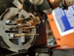
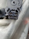
There is something wrong with that ignition switch and connector.
Pull them apart and post pics of both switch and connector.
 

Andi

Member
Joined
Jan 16, 2020
Threads
1
Messages
24
I have three switches...all the same. There is a bit of dielectric grease more so on the switch. The harness is brand new, and I carefully compared every connection before I installed it.
I thought about direct wiring the switch, but when the key is on, I have the proper voltage, so???
 

Attachments

  • Andis husq 4.jpg
    Andis husq 4.jpg
    134 KB · Views: 6
  • Andi Husq 5.jpg
    Andi Husq 5.jpg
    162.2 KB · Views: 6

AVB

Well-Known Member
Joined
Dec 13, 2019
Threads
0
Messages
200
The connector and switch is fine as far as mating. I have same switch and connectors here. The Plastic stand offs is makes it to look like isn't going on completely.

Now there might be damage on the G terminal area of the 7 slot connector or it could just be dielectric grease.
 

Andi

Member
Joined
Jan 16, 2020
Threads
1
Messages
24
It's grease...I have checked all of the connectors.

In a perfect world...where should the battery negative cable be bolted? It is to a frame hole now, but I do not know where it came from. The engine grounds off the harness are connected to the engine on the right side...they are perfect. Why does that darn black wire go...and why does it have 12.34 volts???
I REALLY appreciate all of yalls help. I have been doing 24VDC work for 20 years...and I can not figure this out.
 

Andi

Member
Joined
Jan 16, 2020
Threads
1
Messages
24
Theoretically, if I made a jumper from "A1" to "S" to "B" with (or without) a ground strap...if I plug it into the ignition switch, shouldn't that work?

Even though all but one has been replaced, how do I by-pass the interlock switches and the seat switch and brake switch safety circuits?
 

AVB

Well-Known Member
Joined
Dec 13, 2019
Threads
0
Messages
200
The only difference between 24 VDC and 12VDC circuit is the voltages that you working. To find the bad area when tracing an issue like is to do the voltage drop tests between points. With mower wiring where black in DC in normally ground it can either way because some manufactures tend to AC wiring color codes where black is live and white is the neutral or ground. It can be confusing at times without the wire schematics.

But as far if it interconnect problem since you have 12V on the yellow wire at the solenoid they are all good in reference to the starter circuit so no need to do bypassing there. As far test jump at the switch all you need to jump is the B to S for the starter relay to operate provide the ground return path is intact and that B has 12v on it. Now the engine may run as it probably has a fuel solenoid but what you right now is to get the starter operate.
 

Andi

Member
Joined
Jan 16, 2020
Threads
1
Messages
24
I am going to change the relay and make a new negative battery cable. I'll report back tomorrow AM at latest...as soon as I read voltages again...thanks again
 
Top