How does all of this work. When I put the blade holder, spring and driven disk together, the gears from the driven disk mesh with the gears of the blade holder. Is this correct? Should the clutch spring keep them apart? Since the whole assembly mounts to the camshaft, what allows the blade to disconnect from the motor?
The brake plate is hinged, and the brake spring forces it downward. This causes the pads on the brake plate to contact the driven disk, which helps stop the blade quickly when the lever is released.
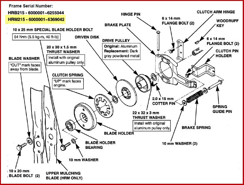
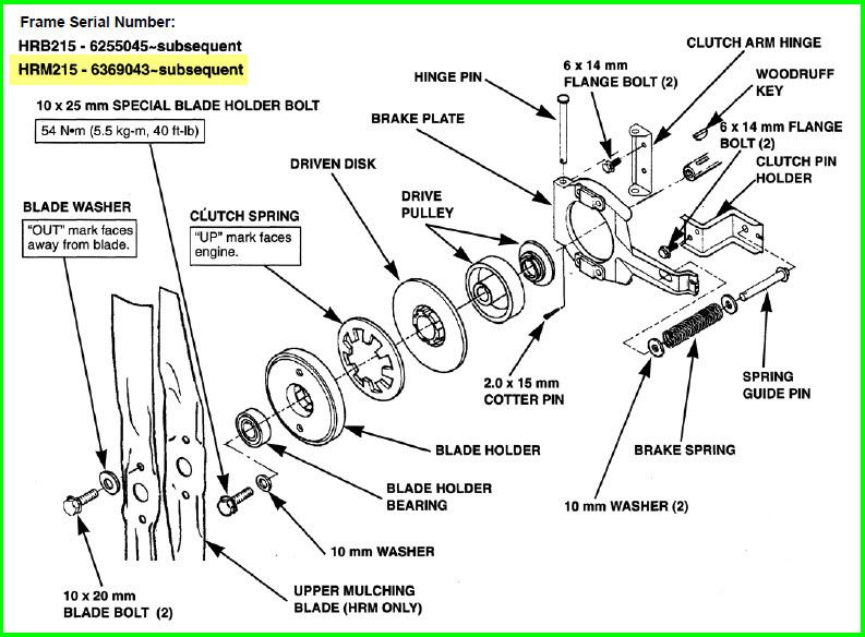
When the operator pulls back on the blade control lever, the driven disk (which is tapered) is pushed upward by the clutch spring and the driven disk contacts the drive pulley (matching taper), which is firmly mounted to the engine's crankshaft. Now the blades are spinning.
When the operator releases the lever, the brake spring forces the brake plate downward, and moves the driven disk away from the drive pulley. The brake pads on the brake plate force the driven disk to stop.
Notes:
* The brake spring is stronger than the clutch spring. This ensures the brake is always applied as well as the blades are de-clutched when the blade control lever is released (no operator present).
* The thrust washers are only used on the original, aluminum drive pulley. Later models (and replacement drive pulleys) are powdered metal, and the thrust washers are not used.