Electrical Issue

Tiger Small Engine

Lawn Addict
Engine: Kohler Command Ch740
Issue: Engine will not start unless jumper wire is hooked to ignition switch on solenoid pole and touched to trigger pole on solenoid. I have three different zero turns that I have experienced this on. Two have Kohler Command engines and one has Vanguard 61E877.

What I have done: Temporarily bypassed, swapped out, and tested the relays, safety switches, ignition switches, and fuses. Cleaned all electrical connections. Did visual inspection of wiring. Tested with multimeter. Checked battery by load testing and checked and confirmed good grounds.
This is driving me crazy. Can someone please help?
Thanks
 
a you got to do actual electrical checks not just swapping parts.

What is the voltage drop at the solenoid trigger terminal using the regular wiring setup?

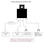
Now if the starter solenoid is even attempting to engage, it maybe dropping a lot of voltage. If so you may need to install a helper relay especially if these have a solenoid shift starter.
 
Solenoids can be random intermittent headaches as we all know. Might work on one testing then immediately fail. Electrical contacts get worn and stop working.

Perfect time for a IR camera. Will SHOW you exactly where the problem is. One bump of the key will spotlight say a bad + connector on the starter for example. Current flow makes heat.

T-Bone on Raley's Small Engines youtube made a video with one. Mower wouldn't crank over. One key bump lit the cable up as hotter than ambient. Time to add another tool to your toolbox.
 
Checked battery by load testing
What type of tester used? Old school carbon pile or the new mOhm meters? I've seen several batteries at Autozone and Oreiley's pass with their new mOhm testers. Took it inside on their real deal carbon pile super tool. Total fail on the pile tester. Guy was like hmmmm. I don't trust these new meters at all.

I would pull the starter off. Bench test it with another say car battery and jumper cables. Get a 100% real deal isolated test. Then go over each cable slash circuit like you have done again.

Make sure on the fuses they don't just fall into the fuse holder. All fuses need to have drag marks on the legs, both sides each leg. No drag marks = a poor connection.
 
a you got to do actual electrical checks not just swapping parts.

What is the voltage drop at the solenoid trigger terminal using the regular wiring setup?

Now if the starter solenoid is even attempting to engage, it maybe dropping a lot of voltage. If so you may need to install a helper relay especially if these have a solenoid shift starter.
Voltage drop is significant at about 4 to 6 volts.
Using regular older style battery tester.
Do have an infrared heat tester. Have only used it on mufflers when testing cylinders.
Fuse holder is holding fuses nice and tight.
Has a piggyback solenoid on the starter. Have not bench tested starter.
 
Then you need to find the source of the voltage drop using point to point voltage tests. Anywhere there is a large voltage is present then that part of the circuit has a large resistance present.

One side note JD years ago had a problem of using long undersized wire runs. Their solution was to add a helper relay.
1779534557654.png
 
If you can post the model number of the machine that has the 4-6 volt loss or a link to a wiring diagram of the machine maybe we can give you some logical tests points to check?

4-6 volts is too much of a voltage drop if you are referring to the starter solenoid trigger post.
I would rig the engine so it does not start when troubleshooting if it starts to crank.
You might have to get a helper and start using the voltmeter and working backwards from the trigger terminal until you find the voltage drop or test at the ign switch and work towards the trigger terminal.
Might just be a bad or corroded connection and adding a helper Auxiliary relay is just bypassing a bad connection or safety switch that will eventually fail later.
Patience is your friend.

See post #2 and #6 also.
 
Last edited:
If you can post the model number of the machine that has the 4-6 volt loss or a link to a wiring diagram of the machine maybe we can give you some logical tests points to check?

4-6 volts is too much of a voltage drop if you are referring to the starter solenoid trigger post.
I would rig the engine so it does not start when troubleshooting if it starts to crank.
You might have to get a helper and start using the voltmeter and working backwards from the trigger terminal until you find the voltage drop or test at the ign switch and work towards the trigger terminal.
Might just be a bad or corroded connection and adding a helper Auxiliary relay is just bypassing a bad connection or safety switch that will eventually fail later.
Patience is your friend.

See post #2 and #6 also.
Model numbers have been given in first post. Still having the issues because I have not been looking at these three zero turn mowers past week. Very busy time of the year. I will break out the multimeter and go for further testing.
 
Model numbers have been given in first post. Still having the issues because I have not been looking at these three zero turn mowers past week. Very busy time of the year. I will break out the multimeter and go for further testing.
All you gave was the base engine model numbers. What is being asked for the equipment model numbers that these engine are on. We need to be looking at the whole wiring schematic not just the engine side.

And in order to find will require you to do point to point voltage drop tests. Basically it is testing the wiring to see if there is voltage between two points when circuit is active where there is to be very close to zero. Example and this will test the whole wiring run including switches and terminals. Place place one meter lead at the ignition switch and the other at the starter trigger terminal and active the circuit. The reading should be zero even though 12v should present when tested to ground. If voltage is present then start breaking the test points into small sections until you find where the voltage is present. Say between the ignition switch and the first safety switch. Also don't forget to test the wiring before the ignition switch. This is done while the circuit is under a load.

Otherwise you are just guessing at the problem. Guess works rarely works and can get expensive.
 
Take note in post #9, You are not checking the voltage to ground with your voltmeter.

You ae checking the voltage drop ACROSS the trigger voltage circuit., which should normally be a low reading of 2 volts or less across the whole circuit.

and this reading is taken under load, ie: while the ignition switch is held in the start position.
 
Back
Top