
You are using an out of date browser. It may not display this or other websites correctly.
You should upgrade or use an alternative browser.
You should upgrade or use an alternative browser.
YTH 2148 wiring diagram
- Thread starter Marine22
- Start date


StarTech
Lawn Royalty
Oh the forget to put the anti rotation device in placed trick.
IF it at the electric clutch one wire is ground and the other is switched 12v. Got to be careful reconnecting as some clutches have a built in diode that short out if connected wrong. And schematic does shows this diode being there.
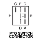
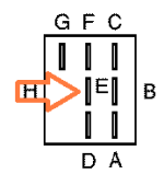
The +12 vdc lead for clutch goes to terminal "E". On the PTO terminal "B" should have +12 vdc when the ignition switch is in the run position. And PTO switch pulled to on position.
Provided you have an PTO clutch with a detachable connector then following should help in connecting up the PTO wires at the clutch. Note red is the +12 vdc wire.
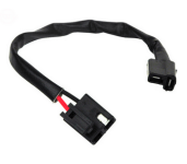
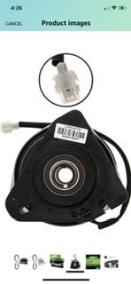
This is Rotary 10-12923.
IF it at the electric clutch one wire is ground and the other is switched 12v. Got to be careful reconnecting as some clutches have a built in diode that short out if connected wrong. And schematic does shows this diode being there.
The +12 vdc lead for clutch goes to terminal "E". On the PTO terminal "B" should have +12 vdc when the ignition switch is in the run position. And PTO switch pulled to on position.
Provided you have an PTO clutch with a detachable connector then following should help in connecting up the PTO wires at the clutch. Note red is the +12 vdc wire.
This is Rotary 10-12923.
Last edited:


StarTech
Lawn Royalty
Sorry been busy in the shop and fighting the heat here. Lost power for several hours in the heat of the day. Boy I though I was off the grid more than I am. Air compressor ran out of air so things got put on hold until the power came back on.
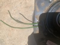
Boy did you get lucky on those PTO the wires usually get rip out their mounting points. And BTW that particular clutch you have is a non polarize version so it doesn't matter which way they connected as long as one is grounded negative and the other positive.
Boy did you get lucky on those PTO the wires usually get rip out their mounting points. And BTW that particular clutch you have is a non polarize version so it doesn't matter which way they connected as long as one is grounded negative and the other positive.