Westwood 12HP Charging Issue

cfmechanics

Member
Joined
Mar 7, 2012
Threads
5
Messages
37
Hello everyone,

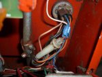
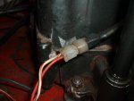
I have had a charging problem with my 12hp Westwood T1200 for a few years now and I have finally got round to fixing it.
The problem basically is my battery is not charging.
I have done a few tests on it using my multimeter and found out the alternator is working correctly.
The battery is new and there are no problems with it.
Electricity is leaving the engine but is not getting to the battery to charge it up.
I have installed a new circuit board so its not that.
My suspicions are its something related to the solenoid?
I have just changed the inline fuses and one was broken so I replaced it and the battery is still the same, no charge so its not that.

I really am stuck if its not the solenoid. :confused2:

Does anyone have any ideas of this? Anything would be much appreciated.

Thanks very much :)

CFMechanics :thumbsup:
 

Attachments

  • P1060986.jpg
    P1060986.jpg
    107 KB · Views: 23
  • P1060987.jpg
    P1060987.jpg
    95.6 KB · Views: 25

Rivets

Lawn Royalty
Joined
Mar 11, 2012
Threads
55
Messages
14,814
I'll try but have some questions. Please post the model numbers of your engine. What test did you do, how did you do them, what were the results of each test. After I read your post I don't think you have a problem with the solenoid, but more likely a bad stator and/or diode. Your numbers will allow me to better picture the wiring and components. I don't know what circuit board you are talking about, maybe we are using different terms, like gas and petro.
 

ILENGINE

Lawn Royalty
Joined
May 6, 2010
Threads
39
Messages
10,112
Are you getting 12v to the connector in the first picture. If so then you need to change the stator, or the diode if you can find one to replace it.

Its a briggs with the 3/5 charging system. 3 amp to the battery, and 5 amp for the headlights.
 

pugaltitude

Lawn Addict
Joined
Jan 11, 2012
Threads
7
Messages
1,142
[/quote] I don't know what circuit board you are talking about, maybe we are using different terms, like gas and petro.[/QUOTE]

Its a small printed circuit board like an ecu but has about 3-4 glass fuses and about 5 dashboard lights.
I would also say its a 2-4 amp charging circuit on the dc wire with the bump at the connector and the other wire is ac for the lights if fitted.
To check the dc side for battery charging you would normally use a dc shunt but because its below 10 amps you can use a multimeter on its own.
Remove white 2 pin connector. Move your lead from volts to 10 amp slot on meter. Red meter wire to connector wire with bump. black wire to battery live. turn dial to amps dc. should get 2-4 amps dc.
If no reading could be diode so test diode or could be stator. if reading there check wiring to solenoid.
To test ac wire put red meter wire back to volt slot. red meter wire to connector wire without diode.
Black meter wire to battery earth. turn dial to volts ac. should get 28 ish upwards volts.
 

cfmechanics

Member
Joined
Mar 7, 2012
Threads
5
Messages
37
Sorry for the slow reply.

I have done a test on the power being produced coming from the alternator.

AC Voltage on tick over - 14.0v
AC Voltage full revs - 37.5v


Does this make sense to anyone?

Thanks for the help :)
 

Rivets

Lawn Royalty
Joined
Mar 11, 2012
Threads
55
Messages
14,814
What voltage do you have across the battery at full speed? I don't understand what you mean by "tick over" please explain.
 

pugaltitude

Lawn Addict
Joined
Jan 11, 2012
Threads
7
Messages
1,142
What voltage do you have across the battery at full speed? I don't understand what you mean by "tick over" please explain.

Tick over means idle like a car pulling up to a junction and stopping. The engine rpm just idles until you drive off and press the accelerator.
Its the british way of explaining how engines run.

Like I posted, battery charge is done by DC amps not AC volts.

"Remove white 2 pin connector. Move your lead from volts to 10 amp slot on meter. Red meter wire to connector wire with bump. black wire to battery live. turn dial to amps dc. should get 2-4 amps dc.
If no reading could be diode so test diode or could be stator. if reading there check wiring to solenoid.
To test ac wire put red meter wire back to volt slot. red meter wire to connector wire without diode.
Black meter wire to battery earth. turn dial to volts ac. should get 28 ish upwards volts"
 

Rivets

Lawn Royalty
Joined
Mar 11, 2012
Threads
55
Messages
14,814
Now I have learn something today so I can go back to bed. I understand that amps charge the battery, but you can have the required amps (2-4) but if you do not have enough push (volts) the battery will not charge. The way I would tell my students is, think of air and a balloon. You may have enough air in your lungs to fill the balloon, but if you can't blow hard enough the balloon will not fill fully. Sorry I can't get out of teacher mode, after five years.
 

pugaltitude

Lawn Addict
Joined
Jan 11, 2012
Threads
7
Messages
1,142
Yes but you can have all the volts in the world but if no amps it wont charge the battery.
Its a bit like the chicken and the egg. What came first??? The chicken, no the egg, no the chicken!
This is why check your amps first as if no amps then could be low to no volts so you are doing 2 tests in one.
DC shunt is the best and quickest test tool to use.
 

Rivets

Lawn Royalty
Joined
Mar 11, 2012
Threads
55
Messages
14,814
I agree, but most people on this forum don't have or even know what a DC shunt is or does. They can easily check voltage, which very seldom gives false results and is a great place for them to start.
 
Top