
You are using an out of date browser. It may not display this or other websites correctly.
You should upgrade or use an alternative browser.
You should upgrade or use an alternative browser.
Toro Proline safety wiring (pistol grip)
- Thread starter Sheltonb
- Start date
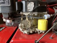
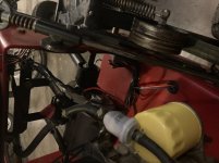
Ok, I’m getting a little better picture of what is going on here, definitely a rewire to by pass safety switches. Here’s what I would do, how you wish to proceed will be up to you. I’ve attached a parts catalog which should help you locate parts on the unit. https://www.toro.com/getpub/25658. Hope you’ve had some electrical experience. Here’s the steps I would follow.
1. Printout the wiring diagram on page 156 of the manual provided earlier.
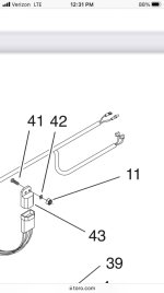
2. Printout pages 4-5 and 8 of the parts catalog I just posted. On these pages located the three safety switches and module which will need to be wired into the circuit. If you look closely at the pictures, you’ll see the approximate location of each switch.
3. Remove the electrical tape from the DIY guys attempt to be a mechanic. Don’t disconnect any plugs.
4. Using the wiring diagram trace all wires following the color code, to identify each component.
5. At this time you should be able to identify where your two unknown wires go.
6. Using temporary wire nuts and test the unit. If it doesn’t work, test the safety switches, for continuity, to see if they are working properly, with a multimeter. This can be done earlier if you want.
7. Hopefully everything works properly, so remove each of the wire nuts, soldering the connection and coat with liquid electrical tape and electrical tape, to protect it.
Warning::: Electrical troubleshooting takes the patience of Job plus a special education teacher, so don’t be afraid to have an assistant around. I’ve done this type of job many times and some take 30 minutes and others have take 2 days. Double check everything you do and then check it one more time. As you go through the procedure don’t think you can remember each step you did, you’ll forget. Take before and after pictures of what you did after each step, they’re easy to delete two weeks after you complete this project. If you have doubts or questions ASK. It’s easier to ask a dumb question, than fix a stupid mistake. There are tech here that know their crap and will be willing to help. Also, each of us do things a little different so don’t think that one might be saying the other is wrong. Good luck.
1. Printout the wiring diagram on page 156 of the manual provided earlier.
2. Printout pages 4-5 and 8 of the parts catalog I just posted. On these pages located the three safety switches and module which will need to be wired into the circuit. If you look closely at the pictures, you’ll see the approximate location of each switch.
3. Remove the electrical tape from the DIY guys attempt to be a mechanic. Don’t disconnect any plugs.
4. Using the wiring diagram trace all wires following the color code, to identify each component.
5. At this time you should be able to identify where your two unknown wires go.
6. Using temporary wire nuts and test the unit. If it doesn’t work, test the safety switches, for continuity, to see if they are working properly, with a multimeter. This can be done earlier if you want.
7. Hopefully everything works properly, so remove each of the wire nuts, soldering the connection and coat with liquid electrical tape and electrical tape, to protect it.
Warning::: Electrical troubleshooting takes the patience of Job plus a special education teacher, so don’t be afraid to have an assistant around. I’ve done this type of job many times and some take 30 minutes and others have take 2 days. Double check everything you do and then check it one more time. As you go through the procedure don’t think you can remember each step you did, you’ll forget. Take before and after pictures of what you did after each step, they’re easy to delete two weeks after you complete this project. If you have doubts or questions ASK. It’s easier to ask a dumb question, than fix a stupid mistake. There are tech here that know their crap and will be willing to help. Also, each of us do things a little different so don’t think that one might be saying the other is wrong. Good luck.
Thank you for this. I really appreciate it. I’ll report backOk, I’m getting a little better picture of what is going on here, definitely a rewire to by pass safety switches. Here’s what I would do, how you wish to proceed will be up to you. I’ve attached a parts catalog which should help you locate parts on the unit. https://www.toro.com/getpub/25658. Hope you’ve had some electrical experience. Here’s the steps I would follow.
1. Printout the wiring diagram on page 156 of the manual provided earlier.
2. Printout pages 4-5 and 8 of the parts catalog I just posted. On these pages located the three safety switches and module which will need to be wired into the circuit. If you look closely at the pictures, you’ll see the approximate location of each switch.
3. Remove the electrical tape from the DIY guys attempt to be a mechanic. Don’t disconnect any plugs.
4. Using the wiring diagram trace all wires following the color code, to identify each component.
5. At this time you should be able to identify where your two unknown wires go.
6. Using temporary wire nuts and test the unit. If it doesn’t work, test the safety switches, for continuity, to see if they are working properly, with a multimeter. This can be done earlier if you want.
7. Hopefully everything works properly, so remove each of the wire nuts, soldering the connection and coat with liquid electrical tape and electrical tape, to protect it.
Warning::: Electrical troubleshooting takes the patience of Job plus a special education teacher, so don’t be afraid to have an assistant around. I’ve done this type of job many times and some take 30 minutes and others have take 2 days. Double check everything you do and then check it one more time. As you go through the procedure don’t think you can remember each step you did, you’ll forget. Take before and after pictures of what you did after each step, they’re easy to delete two weeks after you complete this project. If you have doubts or questions ASK. It’s easier to ask a dumb question, than fix a stupid mistake. There are tech here that know their crap and will be willing to help. Also, each of us do things a little different so don’t think that one might be saying the other is wrong. Good luck.


StarTech
Lawn Royalty
Unwrap the wires to see what the bypasser did. It looks like they removed the wires going to the engine too. The wire with bullet terminal would to the engine under the shroud to the ignition coil kill terminal. The one with the ring terminal would be a ground connection,
I also rotated the image to give a better pov.
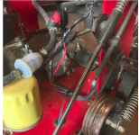
I also rotated the image to give a better pov.