sgkent
Lawn Addict
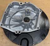
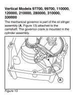
This is on the 125K02-0189-E1 06041958 engine I am rebuilding. When I took it apart, the governor assembly fell off with the sump plate. This is the first time I've had one of these engines apart. When I put it back together, I made some guesses how the governor goes. If someone is familiar with these engines please confirm if this is correct.
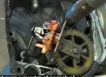
I placed the cam in and lifters etc., making sure the dot and two lines on the cam lined up. The governor mechanism has a steel arm/plate that I put over the end of the cam. I moved the paddle arm on the governor shaft and the governor to where the nose of the governor and the paddle were in contact. I then slide the sump on with the gasket already on the case.
What concerns me is that the governor mechanism doesn't seem to to have anything that holds it in place other than the mesh of its gears with the cam, and the paddle resting on the nose.
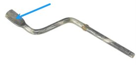
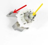
I put the nose (yellow arrow) to the paddle (blue arrow) and placed the engine level so they would not move as I placed the sump on. An old empty clean gallon paint can was perfect to set the engine on for this. The governor/slinger gears meshed with the cam, and the steel mount (red arrow) slid over the cam.
Is this correct?
What keeps things in place once the sump is on?
I placed the cam in and lifters etc., making sure the dot and two lines on the cam lined up. The governor mechanism has a steel arm/plate that I put over the end of the cam. I moved the paddle arm on the governor shaft and the governor to where the nose of the governor and the paddle were in contact. I then slide the sump on with the gasket already on the case.
What concerns me is that the governor mechanism doesn't seem to to have anything that holds it in place other than the mesh of its gears with the cam, and the paddle resting on the nose.
I put the nose (yellow arrow) to the paddle (blue arrow) and placed the engine level so they would not move as I placed the sump on. An old empty clean gallon paint can was perfect to set the engine on for this. The governor/slinger gears meshed with the cam, and the steel mount (red arrow) slid over the cam.
Is this correct?
What keeps things in place once the sump is on?
Last edited: