Powerhouse 500Wi inverter generator no AC output

ttimtucker

Active Member
I'm working on repairing a Powerhouse 500Wi inverter generator where the engine runs fine, but there is no 120vAC output. I'm suspecting that the problem is inside the potted inverter module (in which case I'm probably out of luck) but wanted to see if any advice or suggestions from this forum. I'm attaching the schematic I came up with (can't find one on the internet). As far as I can tell from my resistance measurements, the stator and (what I think is) the rotor/brushes are OK. When I run the engine I get about 30vDC on the 12vDC output, which is way high, but I assume that there is some control from the inverter that is not happening (the voltage applied to the white rotor wires?). I also see about 330vAC on black to black from the stator (which is an input to the inverter module), also way high. The oil sensor would prevent the engine from starting, so I don't think that is a source of the problem. There are no shorts to ground on any of the stator coils, or the rotor. The RPM sensor shows about 100 ohms to ground (so no short, no open); I suppose if the RPM sensor is broken then the inverter module may allow the engine to run too fast, and prevent the AC out from being generated.

Any ideas/advice would be appreciated.
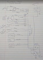
 

Attachments

  • 500wI schematic.jpg
    500wI schematic.jpg
    84.3 KB · Views: 6
I'm working on repairing a Powerhouse 500Wi inverter generator where the engine runs fine, but there is no 120vAC output. I'm suspecting that the problem is inside the potted inverter module (in which case I'm probably out of luck) but wanted to see if any advice or suggestions from this forum. I'm attaching the schematic I came up with (can't find one on the internet). As far as I can tell from my resistance measurements, the stator and (what I think is) the rotor/brushes are OK. When I run the engine I get about 30vDC on the 12vDC output, which is way high, but I assume that there is some control from the inverter that is not happening (the voltage applied to the white rotor wires?). I also see about 330vAC on black to black from the stator (which is an input to the inverter module), also way high. The oil sensor would prevent the engine from starting, so I don't think that is a source of the problem. There are no shorts to ground on any of the stator coils, or the rotor. The RPM sensor shows about 100 ohms to ground (so no short, no open); I suppose if the RPM sensor is broken then the inverter module may allow the engine to run too fast, and prevent the AC out from being generated.

Any ideas/advice would be appreciated.

When I need a break from the multimeter, I head over to how to use bonus in mostbet where the straightforward interface and rewarding perks make it easy to enjoy some high-quality downtime.
Finding three hundred thirty volts AC on the stator and thirty volts on the DC output is a clear indicator that the engine is running without an electrical load because the inverter module has failed to regulate the voltage. Since you have already verified the stator and RPM sensor resistance the issue almost certainly lies within the potted inverter block where a bridge rectifier or a gate driver has likely failed. Before you decide to replace the module you should verify that there is no corrosion in the multi pin connectors and check the continuity of the AC circuit breaker to ensure the output is not just physically disconnected from the panel.
 
Going to be a little hard to replace the inverter module. It is a NLA part.

But the OP can search for himself using PN 71093 Order 60864.
 
I've verified all the external components (breaker, wires) are OK. I will next attempt to "un-pot" the inverter module. Can't make anything more broken than it currently is.
 
Just joined up to add a comment or two, here :geek:

330VAC coming from stator---> is good output.

30 VAC is in ball park for output from the DC winding (nomenclature varies, but "DC winding" is common for the winding that supplies nominal 12 VDC to front panel items). There should be something besides a bridge rectifier, ie a voltage regulator, to bring that down into the 13-18 VDC range. Regulation on the DC circuits on a lot of inverter gens seems a bit 'seat of the pants', from what I've seen.

One of the common failure points on inverter modules are the big DC-link electrolytic capacitors. They are between the input rectification from generator head, and the 120VAC inverter output section. As I understand it, along with smoothing the rectified DC, they also act as reservoirs of energy for surge demands--buying time for inverter module's throttle work, to increase engine RPM. They handle quite a bit of ripply DC, and depending on how the generator is used, can live a pretty hard (and short) life. I'm guessing you know visuals of failed electrolytic caps (domed tops, with or without expelled contents, etc).

They can be replaced by cutting the exposed 'can' off, removing the contents, and soldering replacement caps to the stubs of the original cap--easier than trying to de-pot the entire cap and soldering into the circuit board.

I've seen some Russian youtubes where guys replaced rusted chokes replaced MOSFETs, even rewound bobbins on generator head.

Found an op manual, here:
 
Last edited:
I think it has reached the end of the line for about 10 years of age, especially if it has had a lot of use or weather exposure.

Maybe used parts on eBay, but I doubt it.

James Condon on You Tube is a portable generator guru, and I think he also has a Facebook following. He would be the one to try and contact for more information
 
Back
Top