- Joined
- Feb 19, 2020
- Threads
- 121
- Messages
- 12,898
That's okay as I will DL a copy of the TM2259 for my shop too since I don't have that copy here. GFP hasn't responded to me yet.
Update
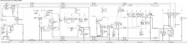
And I just looked over that TM2259 and it appears to be the correct manual. Tnx for the TM PN.
Partial seat switch circuit diagram. Boy I haven't seen a PNP transistor used in a long time.

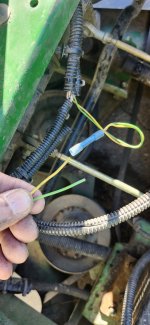
Remove the module and temporary jumper green wires 640 and 641 together. This will bypass the time delay module for test purposes.
Update
And I just looked over that TM2259 and it appears to be the correct manual. Tnx for the TM PN.
Partial seat switch circuit diagram. Boy I haven't seen a PNP transistor used in a long time.
Remove the module and temporary jumper green wires 640 and 641 together. This will bypass the time delay module for test purposes.

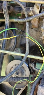
") More schematic studying and wiring tracing to follow.
More schematic studying and wiring tracing to follow.