Interlock question

GeorgiaDave

Forum Newbie
Joined
May 4, 2025
Threads
1
Messages
9
I have just resurrected a Gravely 150 PRO - this is a recoil, not battery start engine. Can anyone tell me or give me a functional schematic of an interlock module for a non-battery powered engine. I understand that the interlock is powered from the ignition coil primary, but I've looked and looked, and can't find any documentation for any module that runs from the primary side of the coil. The interlock is bad, I hate bypassing it, but I also hate that the cost for the interlock is a bit higher than I want to spend (just shy of $200). I have quite a bit of experience with circuit design, but I don't know much about the voltage(s) on the primary side. I suppose I can dig out my o-scope and see for myself, but if anyone here has knowledge regarding this, or an example circuit, I would sincerely appreciate it !

Worst case, I'll buy the interlock, but I'd have a lot more fun building my own...
 

StarTech

Lawn Royalty
Joined
Feb 19, 2020
Threads
110
Messages
12,116
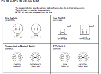
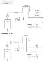
Basically it is a grounding module. Take a little and study the diagram and you should see what I am referring to.

Basically once the tiny circuit board is removed (provided it is one I thinking it is) you will see what a con job it is and how easy you rewire to keep all the safeties fully working as intended.


1746394706882.png
1746394742793.png
1746394640168.png
 
Last edited:

GeorgiaDave

Forum Newbie
Joined
May 4, 2025
Threads
1
Messages
9
No way that I can envision this working without the module. Sure, I can bypass the safety's, that's simple, but that's not what I'm trying to accomplish. I have a failed interlock - rather than buy one, I'd rather build one.

I humbly invite anyone to show how rewiring this circuit can get the safety's functional. Not being negative, but I don't believe it can be done without a module controlling the primary to ground. No, it's not okay to require the handles to be held to run or start ! It has to run in neutral, no PTO, no hands on handlebars. It had to run in gear, with or without PTO, or in neutral, with PTO, or in gear or PTO with hands on handlebar.

I would be exceptionally happy to be proved wrong!

BTW, my Pro 150 is 988059, but same wiring as 988089.
 
Last edited:

StarTech

Lawn Royalty
Joined
Feb 19, 2020
Threads
110
Messages
12,116
Well I would normally sit here and figure this out but right now I dealing a Lower Left Molar tooth giving me a lot of pain and no pain meds to deaden it until at least late Tuesday. I have been in pain since Thursday a week ago. Can't keep my mind on anything long.

I already ran off one nit picking customer Friday that thought lying to me would get me to lower my estimate. Well it did. I just put back in his old transaxle and told him to hit the road Thursday. He came back and got his Friday thinking I installed another transaxle which I didn't. No bill and he is lucky as I could had charged for my time of finding out what was wrong.
 

Auto Doc's

Well-Known Member
Top Poster Of Month
Joined
Sep 7, 2024
Threads
3
Messages
334
I have just resurrected a Gravely 150 PRO - this is a recoil, not battery start engine. Can anyone tell me or give me a functional schematic of an interlock module for a non-battery powered engine. I understand that the interlock is powered from the ignition coil primary, but I've looked and looked, and can't find any documentation for any module that runs from the primary side of the coil. The interlock is bad, I hate bypassing it, but I also hate that the cost for the interlock is a bit higher than I want to spend (just shy of $200). I have quite a bit of experience with circuit design, but I don't know much about the voltage(s) on the primary side. I suppose I can dig out my o-scope and see for myself, but if anyone here has knowledge regarding this, or an example circuit, I would sincerely appreciate it !

Worst case, I'll buy the interlock, but I'd have a lot more fun building my own...
Prove all the safety switches work before you condemn the interlock. It is a simple device that gives the correct go ahead from the switches for safe operations. Likely bugs and connector corrosion has taken place. A simple meter should find your problem.
 

GeorgiaDave

Forum Newbie
Joined
May 4, 2025
Threads
1
Messages
9
Already verified all wiring and switches. Only thing left is the interlock. The unit starts and runs just fine, but only way to turn it off is via the key switch. The safeties are all non-functional.

Likely this forum is the wrong place for electrical questions. Logic tells me that the module is required, but odd that it failed in the wrong direction, I would have expected it to fail with the primary grounded, not open. At least it's usable now, just not very safe...

Thanks!
 

StarTech

Lawn Royalty
Joined
Feb 19, 2020
Threads
110
Messages
12,116
What you are describing is an open circuit.

Even though the wiring is verified have you verified the wire terminals?

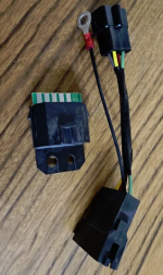
Image of NOS interlock
1746445741578.png

Newer version
1746445889708.png

This show that the mating connector housing would likely have F56/Packard/Dephi female terminals. These do have a habit of breaking at the hinge point thus creating loose connections that may make contact or not.
 

GeorgiaDave

Forum Newbie
Joined
May 4, 2025
Threads
1
Messages
9
Yes, verified all connections, including the terminal blocks. In addition, I also use wire piercing clamps to check all connections (and a touch of liquid sealant on the tiny hole left). The newer version is what I have on my mower. As stated earlier, I would much rather build a replacement than buy and learn something in the process. This is not a customer unit, it's for my brother-in-law who lost everything in Helene; just doing my part to help.

Honestly, I'm just trying to understand the best method to produce steady DC from the primary on the ignition coil. I haven't measured it yet, but I'd expect fairly high and variable voltage on the primary, but obviously it's been done. If I had a spare interlock, I'd remove the potting compound and look at the circuit.

Other than accomplishing DC, it's a simple circuit to reproduce the switch logic. I was hoping maybe someone here had toyed with this. My concern would be loading the primary with the DC conversion and wreaking havoc on the ignition.
 

Auto Doc's

Well-Known Member
Top Poster Of Month
Joined
Sep 7, 2024
Threads
3
Messages
334
I am not aware of any ignition coil producing DC power. The way I read the diagram that is an interlock ignition coil shutdown wire.
Does this engine have only a charging stator under the flywheel to operate lights, or no running power supply system at all?
 

GeorgiaDave

Forum Newbie
Joined
May 4, 2025
Threads
1
Messages
9
It's not DC as we think of it, nor AC. Everytime the magnet passes in front, it causes a magnetic field to form in the ignition coil primary. When the magnet passes, the field collapses causing current to flow in the primary. The primary current causes current to flow in the secondary (not sure of the voltage multiplication, probably at least 100:1) which causes a spark to flow across the spark plug terminals. While this occurs, the primary voltage goes from zero, to perhaps a few hundred volts, then back to zero as the field collapses. The voltage measured would be more AC like than DC, but without any negative component. On an oscope, this will likely show as a very noisy square wave (I'm guessing, haven't hooked mine up yet). The frequency would vary with the motor RPM, which is why I say it's almost AC. The trick would be to convert that noisy square wave to DC to run a safety switching circuit. What I'd like to know is the method the interlock uses to convert that square wave to DC. I'm supposing a cap diode and resistor would do trick, but I was hoping someone here has already figured that part out...

If you turn your flywheel to TDC during the ignition cycle, you'll see the magnet has already moved past the center of the ignition coil - this is how simple engines are timed.
 
Top