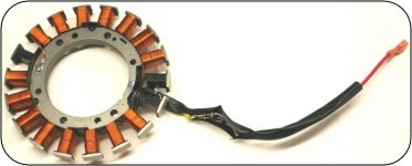
FS600V w/ no regulator or stator?

imagineer

Forum Newbie
Joined
Apr 19, 2023
Threads
3
Messages
8
I have a SCAG 52" walk-behind, hydraulic drive with a Kawasaki FS600V engine and the electric clutch stopped working. I checked the voltage at the wire that I assumed was the output from the voltage regulator and at idle it's outputting 1.7vdc and at full throttle, its putting out about 2.1vdc. So my assumption is the voltage regulator is bad. I took the engine cover off to identify it for a replacement and...there's no voltage regulator. There is a small wire attached to a spade connector on each coil, they're spliced together and a single wire goes to the mower harness (via a bullet connector). This engine also does not appear to have a stator, rather has a simple magneto. There is a single wire coming from under the flywheel, but my understanding is stators have 2 (or 3) wires.


Am I correct in that there is a diode in each coil, and the output from these diodes is the DC voltage used to power the electric clutch? I have replacement coils on order, but I'm curious if there's something else I should be looking it?
 

Auto Doc's

Lawn Addict
Top Poster Of Month
Joined
Sep 7, 2024
Threads
14
Messages
1,124
This sounds like the basic engine has been changed at some point for one with a direct AC charging system and inline diode for battery charging. These do not put out nearly enough amperage to operate an electric PTO for any considerable amount of time.
 

txmowman

Well-Known Member
Joined
Oct 8, 2018
Threads
1
Messages
335
What you have is called a clutch coil. It generates AC voltage but then goes through a pair of diodes that convert the AC to DC to power the clutch. The DC voltage is then “regulated” by the load applied. So, the red wire, unregulated, should read 30+ VDC normally. If not, either the coil is shorted or there is damage to the magnets inside of the flywheel.
 

txmowman

Well-Known Member
Joined
Oct 8, 2018
Threads
1
Messages
335
This sounds like the basic engine has been changed at some point for one with a direct AC charging system and inline diode for battery charging. These do not put out nearly enough amperage to operate an electric PTO for any considerable amount of time.
 

imagineer

Forum Newbie
Joined
Apr 19, 2023
Threads
3
Messages
8
I got lucky and found the service manual. On the FS600V, set up for recoil start, there is a stator under the flywheel and it appears to have a single wire. I'll put the mover back together, get it started and check the voltage at the single wire from the stator.

Also, per the service manual, the recoil stator should have resistance 4.4 to 15 ohms. Given that it's a single wire stator, do I check the resistance between the single wire and a ground point?
 

txmowman

Well-Known Member
Joined
Oct 8, 2018
Threads
1
Messages
335
This sounds like the basic engine has been changed at some point for one with a direct AC charging system and inline diode for battery charging. These do not put out nearly enough amperage to operate an electric PTO for any considerable amount of time.
Its job is to put out to operate the load for as long as needed.
 

imagineer

Forum Newbie
Joined
Apr 19, 2023
Threads
3
Messages
8
What you have is called a clutch coil. It generates AC voltage but then goes through a pair of diodes that convert the AC to DC to power the clutch. The DC voltage is then “regulated” by the load applied. So, the red wire, unregulated, should read 30+ VDC normally. If not, either the coil is shorted or there is damage to the magnets inside of the flywheel.
Thanks. I was checking the voltage at the yellow wire, which is what grounds out the ignition coils to shut off the engine. I'll put it back together tomorrow and check the voltage at the red wire.
 

Auto Doc's

Lawn Addict
Top Poster Of Month
Joined
Sep 7, 2024
Threads
14
Messages
1,124
Hi txmowerman,

I have not seen many single wire stators produce 30+VDC. The stator only produces AC current from the rapidly changing polarity of the spinning magnets attached to the flywheel. Maybe there is a diode hidden in the stator harness I'm not aware of. These were low amperage stators

I've certainly not seen models with an electric PTO clutch and a single wire stator. They don't produce enough amperage to hold the clutch engaged for any length of time. I'm curious how this turns out, because I certainly don't claim I've seen everything.

I've seen the 2-wire stator design produce 30+VAC and then it was converted to DC by the external voltage regulator mounted to the sheet metal for a good ground. Or, they had a separate ground attached to the regulator housing.
 

txmowman

Well-Known Member
Joined
Oct 8, 2018
Threads
1
Messages
335
I got lucky and found the service manual. On the FS600V, set up for recoil start, there is a stator under the flywheel and it appears to have a single wire. I'll put the mover back together, get it started and check the voltage at the single wire from the stator.

Also, per the service manual, the recoil stator should have resistance 4.4 to 15 ohms. Given that it's a single wire stator, do I check the resistance between the single wire and a ground point?
Yes. I would check continuity. If there isn’t any, it is a
Hi txmowerman,

I have not seen many single wire stators produce 30+VDC. The stator only produces AC current from the rapidly changing polarity of the spinning magnets attached to the flywheel. Maybe there is a diode hidden in the stator harness I'm not aware of. These were low amperage stators

I've certainly not seen models with an electric PTO clutch and a single wire stator. They don't produce enough amperage to hold the clutch engaged for any length of time. I'm curious how this turns out, because I certainly don't claim I've seen everything.

I've seen the 2-wire stator design produce 30+VAC and then it was converted to DC by the external voltage regulator mounted to the sheet metal for a good ground. Or, they had a separate ground attached to the regulator housing.
Hi Auto Docs, The coil is actually two separate windings (see attached). Each winding creates full-wave AC. The AC then goes through a diode and gets converted to half-wave pulsating DC. These two half-waves then come together as a full-wave pulsating DC that flows into the load.

It can be seen where each winding goes through a diode. Then the two windings become one red wire to the clutch.

This information is sourced from Kawasaki KTech training. Every technician who works for a Kawasaki dealership should attend this. It is great, and I always learn something.
 

Attachments

  • Picture1.jpg
    Picture1.jpg
    41.7 KB · Views: 1
Top