Charging problem

tommag

Forum Newbie
I'm trying to figure a charging problem out.
The mower is a Ferris stand on, the only ID I found said part # 5901678, serial #2017771044. It has a Kawasaki fx600v engine.
I get good continuity from the regulator to the ignition switch, from there to the fuse, and from the fuse to the battery. At full throttle the AC side of the regulator shows 34v. The dc side showed 25v with the meter on it and the positive battery terminal, 14.8 when hooked to the regulator and negative terminal. After an hour or so at full throttle the battery came up to 11.9v from 11.3v. When I decrease the rpm's it only puts out about 11.5v.
We've been carrying spare batteries and charging them at night. Two of them are older but test good. The other one is about 2 weeks old.
On the suggestion on another thread, I watched Teryl fixes all video dealing with loose magnets. Since I was getting 34v ac I didn't get as far as taking the flywheel off.
Thanks in advance.
Tom
 
I'm trying to figure a charging problem out.
The mower is a Ferris stand on, the only ID I found said part # 5901678, serial #2017771044. It has a Kawasaki fx600v engine.
I get good continuity from the regulator to the ignition switch, from there to the fuse, and from the fuse to the battery. At full throttle the AC side of the regulator shows 34v. The dc side showed 25v with the meter on it and the positive battery terminal, 14.8 when hooked to the regulator and negative terminal. After an hour or so at full throttle the battery came up to 11.9v from 11.3v. When I decrease the rpm's it only puts out about 11.5v.
We've been carrying spare batteries and charging them at night. Two of them are older but test good. The other one is about 2 weeks old.
On the suggestion on another thread, I watched Teryl fixes all video dealing with loose magnets. Since I was getting 34v ac I didn't get as far as taking the flywheel off.
Thanks in advance.
Tom
The first thing you do is properly charge the battery with a battery charger, and then load test. If you are getting 13.5 to 14.5 volts (give or take), at full throttle, then you are good. A flat battery is 12 volts, a fully charged battery at rest is 12.75. If you were starting at 11.3 volts and are now getting 11.9 volts that is a good sign. However, starting with a charged, load tested battery is the way to do it.
 
The dc side showed 25v with the meter on it and the positive battery terminal, 14.8 when hooked to the regulator and negative terminal.
Hmmm is this between the B+ terminal and the positive battery post? If so it should be near zero as you just the circuit between the regulator the the battery post which is essentially a straight piece wire. Some component in that run is creating a huge voltage drop. Like the ignition switch internal contacts, in the fuse holder contacts, or even the wire terminals thenselves.

25 milli volts would more normal not 25 volts as there will a little resistance but that should be the milli ohms.
 
Hmmm is this between the B+ terminal and the positive battery post? If so it should be near zero as you just the circuit between the regulator the the battery post which is essentially a straight piece wire. Some component in that run is creating a huge voltage drop. Like the ignition switch internal contacts, in the fuse holder contacts, or even the wire terminals thenselves.

25 milli volts would more normal not 25 volts as there will a little resistance but that should be the milli ohms.
I may have misread the multimeter as I didn't set the range. Quite possibly it was displaying millivolts and I had a brain fart. I'll check it again when it's brought back this evening. One thing I did miss was checking the regulator's ground. (Read about that in a different thread)
 
Last edited:
Hmmm is this between the B+ terminal and the positive battery post? If so it should be near zero as you just the circuit between the regulator the the battery post which is essentially a straight piece wire. Some component in that run is creating a huge voltage drop. Like the ignition switch internal contacts, in the fuse holder contacts, or even the wire terminals thenselves.

25 milli volts would more normal not 25 volts as there will a little resistance but that should be the milli ohms.
I checked it again and it is 26-27v.
I also checked continuity between the far left terminal of the regulator, the other 2 terminals and the body. It shows no continuity. Between the regulator body and the -terminal of the battery it shows 1.5mv.
With the regulator unhooked the stator pins showed .3 ohms.
 
Last edited:
I'm trying to figure a charging problem out.
The mower is a Ferris stand on, the only ID I found said part # 5901678, serial #2017771044. It has a Kawasaki fx600v engine.
I get good continuity from the regulator to the ignition switch, from there to the fuse, and from the fuse to the battery. At full throttle the AC side of the regulator shows 34v. The dc side showed 25v with the meter on it and the positive battery terminal, 14.8 when hooked to the regulator and negative terminal. After an hour or so at full throttle the battery came up to 11.9v from 11.3v. When I decrease the rpm's it only puts out about 11.5v.
We've been carrying spare batteries and charging them at night. Two of them are older but test good. The other one is about 2 weeks old.
On the suggestion on another thread, I watched Teryl fixes all video dealing with loose magnets. Since I was getting 34v ac I didn't get as far as taking the flywheel off.
Thanks in advance.
Tom
Hello T.,

An Ohm test just confirms there is a connection, but it does not confirm that it can carry a load. An Ohm test can pass with only a single strand of wire holding on for dear life, but the wire cannot carry a load.

Voltage drop testing with your meter set the DC Volts is much more accurate.

Basically, you are testing every wire/cable and connection point when power is applied to see if there is a stray Voltage reading that should not be there. Literally you are testing from point A to point B where a wire connects. The meter will read Voltage if there is a problem.

Crimped battery cable ends are the worst for building internal corrosion inside of the cables.

Study up on Voltage drop testing. It will really open your eyes as to what is likely going on.

I've been an aircraft, automotive and small engine mechanic going on 50+ years in the trade. Electrical problems have been my main focus most of that time. Never trust a connection looks good, prove it's good.
 
The 26-27v DC you are reading should be close to ZERO. It is indicating that you have a bad connection between the center terminal of the regulator and the pos post of the battery. (most generally bad connections are at a fuse holder)
If it's the 3 terminal regulator, The wire that is on the B+ center terminal of the regulator goes through the wire loom and eventually to the POS post of the battery and most generally the connection to the pos battery lead is at the starter solenoid battery terminal.


Can you post a picture of your regulator? (wondering if that is the 3 terminal type reg that has AC on each outside terminals and B+ labeled on the center terminal)

Do you have a ammeter that goes up to at least 15 amps DC?

From your reading you can connect a wire from the center terminal of the regulator (or the B+ terminal of the reg) to the pos post of the bat through a 15 amp fuse and it should charge (show a charge voltage at the battery when you start the engine) because you are bypassing the bad connection. (be sure and use a fuse not over 20 amps inline)

A wiring diagram of the machine would be a good thing.
 
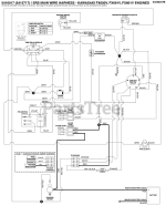
I downloaded the charging system diagram and am a bit overwhelmed, there's a lot here that doesn't seem to be charging related. Would I be correct to assume that the red wires and their connections are the only ones to be checked (along with the ground side)?
ferris diagram.png
 
Forest#2, I don't have a picture of the regulator, but it does have 3 terminals and the right side one is the dc one. I just looked at the manual for my multi meter and it shows 10a max.
 
Just a hint: I would suspect the 20 amp fuse holder and the #3 terminal of the engine harness connector FIRST and next the connection at the starter solenoid terminal
I would check DC voltage across the #3 terminal of the 6 terminal connector and also across the fuse holder with the engine running. As you are testing Zero volts ACROSS is a ok connection and 27 volts is vicinity of the bad connection.
Stay safe with the engine running.

As the guys have indicated Ohms in this case is not an option because it appears to be a high resistance connection when the engine is running. Voltage reading are better for troubleshooting in this case..

Ok, just forget the ammeter for now. (you were typing the same time as I)
 
Last edited:
Back
Top