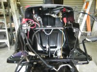
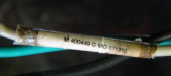
2010 Murray Electrical issue

slomo

Lawn Pro
Joined
Jul 14, 2019
Threads
80
Messages
5,529
That fuse - heavily corroded terminals.

Check pin fitment as in should be very firm to insert. Should see scratches from the female connectors scratching the fuse legs on both legs. If no scratches, take pliers and gently smash the female connectors a bit. Easy here if you do too much, might not get the fuse it.

Looks as the yellow plastic has melted possibly. If so do a real good diag on all the wires and connectors. Look for melted anything.....
 

Auto Doc's

Well-Known Member
Top Poster Of Month
Joined
Sep 7, 2024
Threads
11
Messages
917
I think some of the difference comes down to how the 2 machines are wired.

This Murray (white wire) has to pass through the two safety switches before it goes to the solenoid terminal to trigger it. One of those safety switches could be contributing to the voltage difference when a load is applied.

Disconnect the plugs so the rider will only crank. Set meter to the mV setting. Place you meter leads with one clipped to the battery positive, and then begin at the start solenoid white wire, crank and watch the meter reading. That will show you the true drop of the circuit. Work your way back following the diagram and check each pin at the safety switches. When the meter does not show a drop, go to where it does and there is your problem. If it still shows a considerable drop, it will be on B terminal part of the harness or its connectors/ connections.

Do the same for B terminal feed wire side, both sides of the fuse holder to verify the problem is not with a poor fuse holder pin. I'm still suspicious of that switch power supply wire and it's crimp connections. The power wire to the key switch is connected piggyback to the main battery positive terminal. Corrosion creeps in these and it will mess with the connections that even seem tight. Loosen clean and retighten the power wire and positive cable.

Corroded pins, a bad crimp or the switch itself will be the three suspects.

You would need the product label information off the Husqvarna to get a correct wiring diagram to see the differences. But I think you will pin the problem down doing the voltage drop test method described.

This method of testing seems tedious until you get used to it, but it will become second nature pretty quickly when dealing with issues like this. Ohm testing just tells you there is a wire there. Voltage drop testing tells you if the wire can actually carry a load without dropping it.

Hope this helps you.

There is a guy on You Tube named Dan Sullivan who is a Master Equipment Technician, and he goes into great detail about voltage drop testing. He has a semi-sour personality, but he knows electrical diagnostics from all directions possible.
 

BGS Mex

Member
Joined
Oct 15, 2023
Threads
1
Messages
29
That fuse - heavily corroded terminals.

Check pin fitment as in should be very firm to insert. Should see scratches from the female connectors scratching the fuse legs on both legs. If no scratches, take pliers and gently smash the female connectors a bit. Easy here if you do too much, might not get the fuse it.

Looks as the yellow plastic has melted possibly. If so do a real good diag on all the wires and connectors. Look for melted anything.....
Thank you: The fuse is "normally firm" entering the holder. The latest is that the engine cranks and fires the spark plug whether the seat switch is compressed or not! Yes the engine and everything else is super clean.
 

Attachments

  • Clean Engine.JPG
    Clean Engine.JPG
    100.2 KB · Views: 0
  • DSCF3025.JPG
    DSCF3025.JPG
    123.2 KB · Views: 0

BGS Mex

Member
Joined
Oct 15, 2023
Threads
1
Messages
29
I think some of the difference comes down to how the 2 machines are wired.

This Murray (white wire) has to pass through the two safety switches before it goes to the solenoid terminal to trigger it. One of those safety switches could be contributing to the voltage difference when a load is applied.

Disconnect the plugs so the rider will only crank. Set meter to the mV setting. Place you meter leads with one clipped to the battery positive, and then begin at the start solenoid white wire, crank and watch the meter reading. That will show you the true drop of the circuit. Work your way back following the diagram and check each pin at the safety switches. When the meter does not show a drop, go to where it does and there is your problem. If it still shows a considerable drop, it will be on B terminal part of the harness or its connectors/ connections.

Do the same for B terminal feed wire side, both sides of the fuse holder to verify the problem is not with a poor fuse holder pin. I'm still suspicious of that switch power supply wire and it's crimp connections. The power wire to the key switch is connected piggyback to the main battery positive terminal. Corrosion creeps in these and it will mess with the connections that even seem tight. Loosen clean and retighten the power wire and positive cable.

Corroded pins, a bad crimp or the switch itself will be the three suspects.

You would need the product label information off the Husqvarna to get a correct wiring diagram to see the differences. But I think you will pin the problem down doing the voltage drop test method described.

This method of testing seems tedious until you get used to it, but it will become second nature pretty quickly when dealing with issues like this. Ohm testing just tells you there is a wire there. Voltage drop testing tells you if the wire can actually carry a load without dropping it.

Hope this helps you.

There is a guy on You Tube named Dan Sullivan who is a Master Equipment Technician, and he goes into great detail about voltage drop testing. He has a semi-sour personality, but he knows electrical diagnostics from all directions possible.
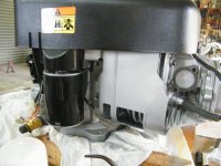
Well; here is the latest! The motor cranks and fires whether the seat Interlock switch is compressed or not; or disconnected from the harness! It does the same with the operable Husvarna switch too. I will check out Dan Sullivan; Thanx.
 

Attachments

  • Thursday July 24, 2025 Motor Cranks and fires with seat switch on or off..pdf
    245.8 KB · Views: 1

Auto Doc's

Well-Known Member
Top Poster Of Month
Joined
Sep 7, 2024
Threads
11
Messages
917
Is the brake/clutch pedal is locked down? On some models that will allow cranking without an operator in the seat to depress the seat switch.
 

BGS Mex

Member
Joined
Oct 15, 2023
Threads
1
Messages
29
Is the brake/clutch pedal is locked down? On some models that will allow cranking without an operator in the seat to depress the seat switch.
Yup; Locked down. How could I ever find out
"On some models that will allow cranking without an operator in the seat to depress the seat switch."
I also tried it with the Brake off (Nothing) and Brake on/Blade off; Nothing. My latest thought is the seat harness connector "Shorting plate". I want to confirm that when the Interlock is attached to the Harness and when the interlock is compressed the middle two pins are "no continuity" to each other. I've had it out of the connector a few times.
 

BGS Mex

Member
Joined
Oct 15, 2023
Threads
1
Messages
29
Well; now here is a development. I re-tested everything with the same results. All the (lawn Tractor) wiring schematics I've looked at are pretty useless in my opinion. I am used to looking at YAMAHA and others like the sample. Has anyone considered the "Blocking Diodes" in the wiring as shown? None of the diagrams show or refer to these. Nothing else make any sense to my small brain. Anyone know how to test for this??? Virtually all the youtube videos concentrate on how to bypass the interlocks; NOT how to properly diagnose issues with them. I can't let this thing go without operating as it was designed.
 

Attachments

  • Seat Interlock wiring connector Harness - Copy.JPG
    Seat Interlock wiring connector Harness - Copy.JPG
    37.8 KB · Views: 3
  • Ignition Switch Yellow (L) - Copy.JPG
    Ignition Switch Yellow (L) - Copy.JPG
    72.7 KB · Views: 2
  • Yamaha VX 700 Diagram.pdf
    352.5 KB · Views: 5
Top