Murray 30" Rear Engine Mower - Switch Help (does not turn off)

fixit_joe

Forum Newbie
Hello,

I inherited a 1999 Murray 30" Rear Engine mower with a Briggs & Stratton Model #: 28B707 engine. Ever since the beginning the mower does not shut off when the switch is turned to the off position. I have been choking the carburetor to stall the motor to turn it off. Now I'd like to re-wire it correctly so it shuts off when turned to the off position. I am not famiiar with electrical work or lawn riding lawn mowers. I consider myself a handy person and have rebuilt the carburetor in the past for the mower.

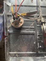
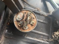
I am attaching two pictures of the switch with the harness and the switch itself. It seems the two yellow wires have been cut and electric tape put on the ends. Can anyone tell me how I can wire the switch to shut off?
IMG_2172.jpg

IMG_2173.jpg
 
Those wires are the circuit to shut it off. Why they are cut is hard to say. Likely someone trying to compensate for a bad safety switch.
 
To get it working at least at the switch, you need to hook the double wires to the terminal on the ignition coil, as it grounds out the ignition to shut it down.
However, you must be careful not to send any voltage to your coil, as that will damage it badly.
 
i would get a multimeter, set to continuity (beep, if it has it) and see which terminal is Grounded to frame when in the off position.
 
That switch, the G post is grounded to the outer metal of the switch, and that wire should go to the frame. The M terminal post goes to the kill post on the coil. But yes, one should check for stray voltage, as that will destroy the coil.
 
That switch, the G post is grounded to the outer metal of the switch, and that wire should go to the frame. The M terminal post goes to the kill post on the coil. But yes, one should check for stray voltage, as that will destroy the coil.
Thank you all for assisting me. So I should check that the wire for the G post grounds to the frame? I can check this by putting the switch to the off position and checking continuity using a multimeter. The two yellow wires for the M post should be a single wire going to the kill post on the ignition coil? Is that correct.
 
Last edited:
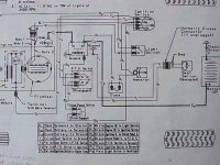
This is the schematic for a Murray tractor rider from around 1988. Maybe it's close enough to help or it may be the exact .

I'd like to see you kill it with the electric system rather than the choke.

1639961438967.jpeg
 
If this is the correct schematic, then you have an electric pto, so following the diagram becomes more necessary, as one of those yellow wires goes to a circuit for the pto switch. One of them goes to the terminal on the coil, and the other one goes through a bunch of safety switches.
 
If this is the correct schematic, then you have an electric pto, so following the diagram becomes more necessary, as one of those yellow wires goes to a circuit for the pto switch. One of them goes to the terminal on the coil, and the other one goes through a bunch of safety switches.
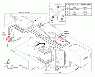
Here is the correct electrical diagram for the riding lawn mower. I've highlighted two limit switches that are not present on my mower. My thought was to bypass them all together.

electrical diagram.gif
 
Back
Top