You are using an out of date browser. It may not display this or other websites correctly.
You should upgrade or use an alternative browser.
You should upgrade or use an alternative browser.
Export thread
Small Engine novice
#1
R
rklemm60
R
rklemm60
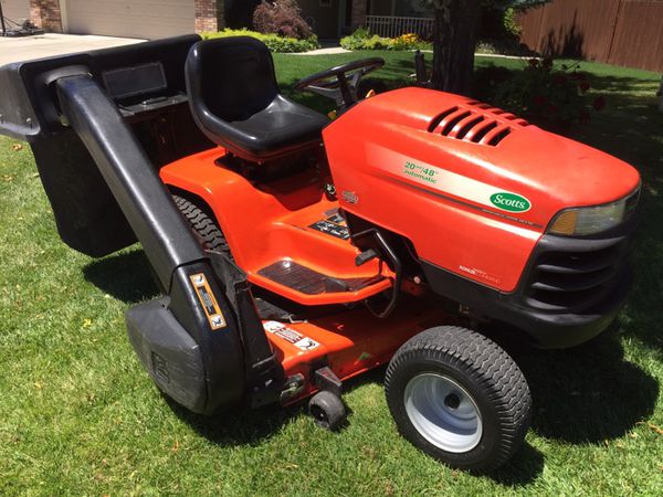
Hi, My neighbor passed away and told his girl friend to give me his kohler command 20hp rider to me because I was the only neighbor who was friendly to this immigrant from Cambodia. He kept his rider in get condition and I was able to run it several times last winter. Then after sitting around for a couple of months, then engine does not want to turn over and I have no way of getting it to a small engine mechanic so I hope to get some assistance
#2
B
Born2Mow
B
Born2Mow
One Question: Is the fuel tank mounted HIGHER than the carb ?
This is a common design on smaller mowers & garden tractors, and it is also the kiss if death. Gravity pulls fuel into the carb where it ends up in the combustion chamber and/or in the engine oil. The only fuel shut off valve you can trust are the manual ones. And you MUST use it religiously.

Take out the spark plug and drain all the engine oil. Spin the engine. You may see raw fuel come out the muffler. Allow it to "air out" for 24 hrs. Install the new fuel shut off, new engine oil, a new spark plug and fresh fuel. (You can pour all the old fuel into your car because it won't care.)
Cars never have this issue because the fuel tank is BELOW the fuel intake system. Also, cars have a computer to sense poor quality fuel.
This is a common design on smaller mowers & garden tractors, and it is also the kiss if death. Gravity pulls fuel into the carb where it ends up in the combustion chamber and/or in the engine oil. The only fuel shut off valve you can trust are the manual ones. And you MUST use it religiously.
Take out the spark plug and drain all the engine oil. Spin the engine. You may see raw fuel come out the muffler. Allow it to "air out" for 24 hrs. Install the new fuel shut off, new engine oil, a new spark plug and fresh fuel. (You can pour all the old fuel into your car because it won't care.)
Cars never have this issue because the fuel tank is BELOW the fuel intake system. Also, cars have a computer to sense poor quality fuel.
#3
R
Rivets
R
Rivets
You have come to the right place to help you out, but you need to provide us with more info so we know where to start. Please answer the following questions and someone will get back to you as soon as possible. It may take some time but I’m 95% sure we’ll be able to help you solve the problem, while keeping the costs down. At this point, please do not start throwing any parts at it until we can find the cause of your problem. Most of the time the DIY guys spend more than necessary trying to see what sticks to the wall.
1. What is the make of your unit along with all numbers from the ID tag.
2. What is the make of the engine along with all numbers from the ID tag.
3. When “you say it doesn’t turn over “. do you mean absolutely nothing happens when you turn the key?
4. Do you have a DC test light or small VOM to test electrical circuits? If yes the first thing to test is battery voltage.
5. Did you replace the old fuel with fresh fuel?
6. What have you done so far to solve the problem.
#4
R
rklemm60
1. Its a Scotts 20 hp made by John Deer S-2048
2. Its a Kohler command 20 #2408301
3. yes, absolutely nothing happens
4. I use a multi-meter to test circuits and I just replaced the 12 volt battery and it is showing 12.5 volts
5. Last winter I never tried to start it until I had replaced all the old gas with fresh fuel. It ran great all winter
I pulled the switch and cleaned it. I identified all the lead markings. I tried to bypass the switch. I tried to connect two unconnected wires - a red to a white (that created a spark). I have started it dozens of times last winter. please see attached photos.


R
rklemm60
Thank you so much for you timely response. Let me answer your questions using your numbers:You have come to the right place to help you out, but you need to provide us with more info so we know where to start. Please answer the following questions and someone will get back to you as soon as possible. It may take some time but I’m 95% sure we’ll be able to help you solve the problem, while keeping the costs down. At this point, please do not start throwing any parts at it until we can find the cause of your problem. Most of the time the DIY guys spend more than necessary trying to see what sticks to the wall.
1. What is the make of your unit along with all numbers from the ID tag.
2. What is the make of the engine along with all numbers from the ID tag.
3. When “you say it doesn’t turn over “. do you mean absolutely nothing happens when you turn the key?
4. Do you have a DC test light or small VOM to test electrical circuits? If yes the first thing to test is battery voltage.
5. Did you replace the old fuel with fresh fuel?
6. What have you done so far to solve the problem.
1. Its a Scotts 20 hp made by John Deer S-2048
2. Its a Kohler command 20 #2408301
3. yes, absolutely nothing happens
4. I use a multi-meter to test circuits and I just replaced the 12 volt battery and it is showing 12.5 volts
5. Last winter I never tried to start it until I had replaced all the old gas with fresh fuel. It ran great all winter
I pulled the switch and cleaned it. I identified all the lead markings. I tried to bypass the switch. I tried to connect two unconnected wires - a red to a white (that created a spark). I have started it dozens of times last winter. please see attached photos.
Attachments
#5
R
Rivets
R
Rivets
Look behind the left rear wheel or under the seat, should be an ID tag with model numbers. Hook the plugs back up the way they were. We will try to find a wiring diagram and from that point we can start to solve your problem. This is going to be slow, because I’m guessing we are going to find multiple problems, the result of you trying to jump the switch. Be patient and we’ll get through this.
#6
B
bertsmobile1
Good news for you is I have that manual and there is only 1 wiring diagram so I will post it below
Bad news is it is from a locked file so it is a screen shot which are never as clear as they could be
So the las thing we need to know is which ignition you have as there were 2 different ones used as depicted in the far right section
The Smart Advance ( called SAM ) and the plain magneto
To work out which you have remove the blower housing and look at the coils , only 1 white wire = std magneto , 2 wires ( yellow & brown ) = SAM
Worse news is as I predicted the magneto kill wire is the white while so if you connected that to power you have just cost yourself $ 80 to $ 150
JD use a 30 amp fuseable link between the battery & the alternator wire for recharging and a 15A fuse to protect the wiring on the red wire to the key switch.
I will guess that the extra red wire on the battery , the one that does not go through terminal cover , is a 1/2 wits attempt to overcome a blown fuseable link ( heavy blue wire )
Now the big question is can you understand this wiring diagram
From my time on various forums it appears that less than 0.01% of American can actually manage this basic high school education feat .
If not let us know so we can walk you through it and hopefully fix your butchered mower
Please note the K1 START RELAY is the proper name for the solenoid
To energise the starter the purple wire needs to be battery voltage when the key is in the start position.

B
bertsmobile1
Well now we are getting some whereThank you so much for you timely response. Let me answer your questions using your numbers:
1. Its a Scotts 20 hp made by John Deer S-2048
2. Its a Kohler command 20 #2408301
3. yes, absolutely nothing happens
4. I use a multi-meter to test circuits and I just replaced the 12 volt battery and it is showing 12.5 volts
5. Last winter I never tried to start it until I had replaced all the old gas with fresh fuel. It ran great all winter
I pulled the switch and cleaned it. I identified all the lead markings. I tried to bypass the switch. I tried to connect two unconnected wires - a red to a white (that created a spark). I have started it dozens of times last winter. please see attached photos.
Good news for you is I have that manual and there is only 1 wiring diagram so I will post it below
Bad news is it is from a locked file so it is a screen shot which are never as clear as they could be
So the las thing we need to know is which ignition you have as there were 2 different ones used as depicted in the far right section
The Smart Advance ( called SAM ) and the plain magneto
To work out which you have remove the blower housing and look at the coils , only 1 white wire = std magneto , 2 wires ( yellow & brown ) = SAM
Worse news is as I predicted the magneto kill wire is the white while so if you connected that to power you have just cost yourself $ 80 to $ 150
JD use a 30 amp fuseable link between the battery & the alternator wire for recharging and a 15A fuse to protect the wiring on the red wire to the key switch.
I will guess that the extra red wire on the battery , the one that does not go through terminal cover , is a 1/2 wits attempt to overcome a blown fuseable link ( heavy blue wire )
Now the big question is can you understand this wiring diagram
From my time on various forums it appears that less than 0.01% of American can actually manage this basic high school education feat .
If not let us know so we can walk you through it and hopefully fix your butchered mower
Please note the K1 START RELAY is the proper name for the solenoid
To energise the starter the purple wire needs to be battery voltage when the key is in the start position.
#7
R
rklemm60


R
rklemm60
Thank you for your reply. I reconnected the starter switch as you suggested and found a tag with the model number but it was hard to read. I checked under the seat and all around the rear left tire, but, found this tag on the perpendicular side of the rear trailer hitch. Hopefully this information helps. Unfortunately, I had to take screen shots in order to get these on to your server.Look behind the left rear wheel or under the seat, should be an ID tag with model numbers. Hook the plugs back up the way they were. We will try to find a wiring diagram and from that point we can start to solve your problem. This is going to be slow, because I’m guessing we are going to find multiple problems, the result of you trying to jump the switch. Be patient and we’ll get through this.
Look behind the left rear wheel or under the seat, should be an ID tag with model numbers. Hook the plugs back up the way they were. We will try to find a wiring diagram and from that point we can start to solve your problem. This is going to be slow, because I’m guessing we are going to find multiple problems, the result of you trying to jump the switch. Be patient and we’ll get through this.
Attachments
#8
S
slomo
S
slomo
For one, that left pic, is the key switch right? See that green puss on the terminal side? That switch is bad.
And all that black house Romex wire is crazy.
Second pic from the left. See that green puss in the connector? Not good......
Lots of experimental wiring going on.
Get a cheap soldering iron and some marine grade heat shrink with the adhesive inside. Go to town on that mower.
And all that black house Romex wire is crazy.
Second pic from the left. See that green puss in the connector? Not good......
Lots of experimental wiring going on.
Get a cheap soldering iron and some marine grade heat shrink with the adhesive inside. Go to town on that mower.
#9
B
bertsmobile1
B
bertsmobile1
This is getting way too confusing as there are multiple threads happening
rklemm60 has energised the magneto kill wires so has fried both of his magneto coils so no matter what is done it will not start till they are replaced .
Star recognised the engine as having standard coils so at least he will not need to replace the SAM .
As he mentioned it was owned by a Cambodian immigrant , a person from a country where replacement parts do not exist so any broken item gets worked around , fixed or bodged .
SO the wiring will need to be properly checked
I have already suggested rklemm60 purchase the JD Tech Manual & Star has identified the correct one.
I found I had one on file so posted the wiring diagram.
In the other thread Star also posted the switch connections , so all the necessary information is there .
Right now I am waiting to find out is rklemm60 can understand wiring diagrams before going further .
As he got the mower for nothing IMHO as the price of the manual & coils is about 10% of the price of a used mower so it is a no brainer .
Looks like it was used to push snow as well so I would expect to see a fair bit of corrosion on the terminal plugs and would not be surprised if they key switch is bad
I could just about guarantee that the fuseable link has blown .
I usually replace them with a big fuse or circuit breaker
So now we wait for the owner to come back before we can help him with a repair plan
#10
R
Rivets
R
Rivets
Bert, I agree with you. I guess we will have to be patient also. Rk, would you tell us what happens after you removed all your jumpers and also how well you understand electrical wiring, diagrams and troubleshooting? This will tell us if you can fix this with our help.
#11
R
rklemm60
R
rklemm60
Thank you so much for finding this wiring diagram!! I am working on getting the blower cover off so I can distinguish between SAM and Magneto. This is really encouraging!!Well now we are getting some where
Good news for you is I have that manual and there is only 1 wiring diagram so I will post it below
Bad news is it is from a locked file so it is a screen shot which are never as clear as they could be
So the las thing we need to know is which ignition you have as there were 2 different ones used as depicted in the far right section
The Smart Advance ( called SAM ) and the plain magneto
To work out which you have remove the blower housing and look at the coils , only 1 white wire = std magneto , 2 wires ( yellow & brown ) = SAM
Worse news is as I predicted the magneto kill wire is the white while so if you connected that to power you have just cost yourself $ 80 to $ 150
JD use a 30 amp fuseable link between the battery & the alternator wire for recharging and a 15A fuse to protect the wiring on the red wire to the key switch.
I will guess that the extra red wire on the battery , the one that does not go through terminal cover , is a 1/2 wits attempt to overcome a blown fuseable link ( heavy blue wire )
Now the big question is can you understand this wiring diagram
From my time on various forums it appears that less than 0.01% of American can actually manage this basic high school education feat .
If not let us know so we can walk you through it and hopefully fix your butchered mower
Please note the K1 START RELAY is the proper name for the solenoid
To energise the starter the purple wire needs to be battery voltage when the key is in the start position.
View attachment 65779
#12
R
rklemm60
R
rklemm60
Yes, the switch on the left is the key switch. I do have a red wire servicing an add on wench on the tractor, Maybe that is part of what is requiring more crazy wiring.For one, that left pic, is the key switch right? See that green puss on the terminal side? That switch is bad.
And all that black house Romex wire is crazy.
Second pic from the left. See that green puss in the connector? Not good......
Lots of experimental wiring going on.
Get a cheap soldering iron and some marine grade heat shrink with the adhesive inside. Go to town on that mower.
#13
R
rklemm60
R
rklemm60
I did wire my new kitchen, but the 9 circuits were all new and youtube instructed me on how to successfully hooked up a four way switch, but I have no experience with tractor wiring. I would appreciate your help. Unfortunately I work 9 hours a day m - f. I can only work in the evenings and on weekends. I appreciate your willingness to walk me through this. I almost have the blower cover off the unit.Bert, I agree with you. I guess we will have to be patient also. Rk, would you tell us what happens after you removed all your jumpers and also how well you understand electrical wiring, diagrams and troubleshooting? This will tell us if you can fix this with our help.
#14
R
rklemm60
R
rklemm60
I am currently in the process of removing the blower cover so I am distinguish whether I have a SAM or a Magneto coil but it sounds like you have already determined it is magneto and I have fried both. Is it possible to test the magnetos once I pull them. If not, I will start looking for a pair of Magneto coils if that is advisable. As for the snow, my cambodian friend used a proper snow blower. We haven't had enough snow to justify using this tractor. Also, regarding the battery, I just purchased it last weekend. The battery I bought last oct was defective and only putting out 3 volts after a charge. This new one is putting out 12.5 volts. Also, regarding my cambodian friend, he was a mechanic by trade and ran his own shop along with his vietnamese wife. He also gave me a wood chipper and a gaseline powered edger. Both were well maintained with fresh oil, no bad gas, and they started up the first try. I hope this information helps you help me.This is getting way too confusing as there are multiple threads happening
rklemm60 has energised the magneto kill wires so has fried both of his magneto coils so no matter what is done it will not start till they are replaced .
Star recognised the engine as having standard coils so at least he will not need to replace the SAM .
As he mentioned it was owned by a Cambodian immigrant , a person from a country where replacement parts do not exist so any broken item gets worked around , fixed or bodged .
SO the wiring will need to be properly checked
I have already suggested rklemm60 purchase the JD Tech Manual & Star has identified the correct one.
I found I had one on file so posted the wiring diagram.
In the other thread Star also posted the switch connections , so all the necessary information is there .
Right now I am waiting to find out is rklemm60 can understand wiring diagrams before going further .
As he got the mower for nothing IMHO as the price of the manual & coils is about 10% of the price of a used mower so it is a no brainer .
Looks like it was used to push snow as well so I would expect to see a fair bit of corrosion on the terminal plugs and would not be surprised if they key switch is bad
I could just about guarantee that the fuseable link has blown .
I usually replace them with a big fuse or circuit breaker
So now we wait for the owner to come back before we can help him with a repair plan
#15
B
bertsmobile1
B
bertsmobile1
I have asked the moderator to close one of your two threads as it is getting very confusing so do not be surprised if this happens.
We shoould have gotten you to delete one way back but too late for that now .
Coils have a chip in then that basically replaces the points, if you are old enough you might remember points .
On a std magneto the chip is embedded inside the coils which then became "Modules" and increased in price by 4 to 8 times .
The SAM system has the chip in a remote module that allows the timing to advance or ****** so these engine have a lot more torque .
Overall it was a failure so got abandoned .
The timing chips all work on negative voltages and are destroyed if they get battery voltage.
As they are not repairable it is a simple test
Works or replace
The test for the single wire one is to remove the white ( in your case ) kill wire from the coil and crank the engine
No spark = replace .
Testing a SAM system is a little more complicated
IF you buy the manual I suggested you will find it covers both the mower & engine and the engine section is actually better than the offical Kohler manual
It i a big manual ( around 300 pages ) with hundreds of photos so way too big to be sent as an email or attached to this thread
#16
B
bertsmobile1
B
bertsmobile1
As for your friend
Firstly thank you for being a good human being and accepting him into your country & community
More people like you would actually make the USA GREAT AGAIN regardless of what a former disgraced yet still very popular president says.
We got a lot of SE Asian reffugees down here that originally we treated very well then there was a change of government and the current populist racist stance makes me ashamed to be called an Australian .
I have a lot of SE Asian imigrants in my run who have taken up market gardening and all of them a fine people .
However the things they do to keep their equipment running while being quite inventive , makes me cringe every time they phone.
OTOH once shown how to do the job properly they will do it.
All of them said the same thing that arm tooling was all bought on the black market so there was no factory service and even fewer parts available so work around were the normal .
#17
R
Rivets
R
Rivets
Rk, I’m going to go into instructor mode to help everyone out. Star, Bert and myself have all have had hundreds of hours electrical troubleshooting, but we will all have a problem, unless we follow a couple of simple rules.
First, we understand that your ability to troubleshoot DC electrical systems is limited, as troubleshooting DC circuits is very different than troubleshooting AC circuits.
Second, we are hundreds, if not thousands of miles from you and can not see what you see.
That being said if we ask a question, please be as specific as possible with your answer. Remember you are our eyes and ears with this project, so we must rely on you to paint us the best picture possible. Also, in electrical troubleshooting you “NEVER ASSUME ANYTHING“ if you don’t understand something we tell you, don’t be afraid to ask for clarification. Remember, it is better to ask a stupid question than make a dumb mistake.
To start with please reread all posts and answer as many of the questions we ask as possible. Post #10 is very important as we need to know what you feel your ability with DC circuits is. If you can’t answer a question don’t worry about it. Together we’ll get this worked out.
#18

StarTech
StarTech
I don't any question stupid when the person asking it don't know the answer. Now I got a brother that if you ask a question and if he knows the answer he will not tell you as he thinks you should know the answer too. Just being a jerk.
#19
R
rklemm60
R
rklemm60
Thank you so much!! that should be fine to remove the two threads. thanks for explaining the transition from points to modules. one question, I understand removing the kill wire from the coil, but, this kohler has no pull cord and the switch doesn't work, so how would I test for spark?I have asked the moderator to close one of your two threads as it is getting very confusing so do not be surprised if this happens.
We shoould have gotten you to delete one way back but too late for that now .
Coils have a chip in then that basically replaces the points, if you are old enough you might remember points .
On a std magneto the chip is embedded inside the coils which then became "Modules" and increased in price by 4 to 8 times .
The SAM system has the chip in a remote module that allows the timing to advance or ****** so these engine have a lot more torque .
Overall it was a failure so got abandoned .
The timing chips all work on negative voltages and are destroyed if they get battery voltage.
As they are not repairable it is a simple test
Works or replace
The test for the single wire one is to remove the white ( in your case ) kill wire from the coil and crank the engine
No spark = replace .
Testing a SAM system is a little more complicated
IF you buy the manual I suggested you will find it covers both the mower & engine and the engine section is actually better than the offical Kohler manual
It i a big manual ( around 300 pages ) with hundreds of photos so way too big to be sent as an email or attached to this thread
#20
R
rklemm60
R
rklemm60
Thank you. I will re-read all the posts and make sure I have answered all the questions with as much specificity as possible and I will try to get you pictures that we need to solve this project. I am blown away by the patience you have with somebody that only has a couple hours a day to work on this until this weekend when I will have more time. WRT DC circuits, I am not comfortable. I believe you are going to have to walk me through step by step.Rk, I’m going to go into instructor mode to help everyone out. Star, Bert and myself have all have had hundreds of hours electrical troubleshooting, but we will all have a problem, unless we follow a couple of simple rules.
First, we understand that your ability to troubleshoot DC electrical systems is limited, as troubleshooting DC circuits is very different than troubleshooting AC circuits.
Second, we are hundreds, if not thousands of miles from you and can not see what you see.
That being said if we ask a question, please be as specific as possible with your answer. Remember you are our eyes and ears with this project, so we must rely on you to paint us the best picture possible. Also, in electrical troubleshooting you “NEVER ASSUME ANYTHING“ if you don’t understand something we tell you, don’t be afraid to ask for clarification. Remember, it is better to ask a stupid question than make a dumb mistake.
To start with please reread all posts and answer as many of the questions we ask as possible. Post #10 is very important as we need to know what you feel your ability with DC circuits is. If you can’t answer a question don’t worry about it. Together we’ll get this worked out.
#21
R
rklemm60
R
rklemm60
I appreciate your comments and understand we may run into some wonki wiring problems here based on what you said, however, this tractor ran like a champ all winter and I am hoping the problems getting this running were purely caused by my trying to bypass the switch based on a youtube demonstration on a switch that did not match my switch. Also, I connected a the wire on the positive battery lead to a white unconnected wire which produced a spark and made the wire very hot after a couple of attempts.As for your friend
Firstly thank you for being a good human being and accepting him into your country & community
More people like you would actually make the USA GREAT AGAIN regardless of what a former disgraced yet still very popular president says.
We got a lot of SE Asian reffugees down here that originally we treated very well then there was a change of government and the current populist racist stance makes me ashamed to be called an Australian .
I have a lot of SE Asian imigrants in my run who have taken up market gardening and all of them a fine people .
However the things they do to keep their equipment running while being quite inventive , makes me cringe every time they phone.
OTOH once shown how to do the job properly they will do it.
All of them said the same thing that arm tooling was all bought on the black market so there was no factory service and even fewer parts available so work around were the normal .
#22
V
VegetiveSteam
V
VegetiveSteam
I may as well ask a question or two of RK and throw my opinion in.
Before you took anything apart and started jumping wires, what exactly did the machine do when you turned the key to try and start the engine? Did it do absolutely nothing as if someone had removed the battery?
I ask this because before you dive in too deep with wiring diagrams and such, a couple of very simple voltage tests might help determine if the issue is an engine issue or an equipment issue. Actually reading my post will take longer than the actual testing.
It looks like you may have already done one of the tests. If that red wire you unfortunately jumped to the white "ground to kill" lead connected to the B terminal on the key switch then the question of, "do you have power getting to the key switch" looks to be a definite yes.
The second test I would do since you have easy access to the key switch is, plug the key switch back in. Assuming you didn't blow the fuse by shorting power to the white wire, and you still have power on that red wire, take your voltmeter set to DC volts of course and put the black lead of the meter on a known good ground. Now take the red lead and touch only the S terminal on the key switch once it is plugged back into it's connector. Once you find which wire connects to the S terminal it might be easier to gently probe it from the back side of the connector but don't pierce the wire itself. Now, turn the key to the start position? Do you now get voltage on that S terminal?
If have no power to the S terminal you more than likely need a new key switch. If you do now have voltage on that S terminal there is one more simple test. After that, it may be time for the wiring diagrams. Get the engine to crank first and then you can worry about if you damaged the ignition modules or not.
So, if in the previous test you did indeed get power to the S terminal of the key switch when you turned the key to the start position, the next test will be at the starter itself. Find the small spade terminal on the starter solenoid. If the start circuit goes through the Kohler wire harness that wire I call the excite wire will be blue. Sometimes the OEM of the equipment has the engine built so it runs off their wire directly from the key switch. If that's the case that wire will probably not be blue but either way it's the only single spade terminal on the solenoid.
This is where you may need another person to help you. Again attach the black lead of your voltmeter to a known good ground. Now take the red lead and while leaving that excite wire connected to the starter spade terminal, touch the exposed portion of the spade and have your helper while sitting in the seat, turn the key to the start position. Do you read battery voltage at that spade terminal now? If you do have battery voltage at that spade terminal you probably have a ground issue.
If only it were that simple right?
#23

Tiger Small Engine
Remove the engine shroud (top black plastic cover). Pull the white wire off of the ignition coil(s). Take the spark plug out and reconnect to HT lead (spark plug wire). Rest the spark plug against the metal part of engine to create ground. Crank the engine with key switch and watch for spark. Repeat procedure with white kill wire attached to ignition coil. If no spark with kill wire attached then replace coil(s).
Tiger Small Engine
Testing for spark:Thank you so much!! that should be fine to remove the two threads. thanks for explaining the transition from points to modules. one question, I understand removing the kill wire from the coil, but, this kohler has no pull cord and the switch doesn't work, so how would I test for spark?
Remove the engine shroud (top black plastic cover). Pull the white wire off of the ignition coil(s). Take the spark plug out and reconnect to HT lead (spark plug wire). Rest the spark plug against the metal part of engine to create ground. Crank the engine with key switch and watch for spark. Repeat procedure with white kill wire attached to ignition coil. If no spark with kill wire attached then replace coil(s).
#24
B
bertsmobile1
Spark without wires on + no spark wires off = bad wiring on mower
No spark wires off = bad coils , replace them
B
bertsmobile1
Got it backwards there TigerTesting for spark:
Remove the engine shroud (top black plastic cover). Pull the white wire off of the ignition coil(s). Take the spark plug out and reconnect to HT lead (spark plug wire). Rest the spark plug against the metal part of engine to create ground. Crank the engine with key switch and watch for spark. Repeat procedure with white kill wire attached to ignition coil. If no spark with kill wire attached then replace coil(s).
Spark without wires on + no spark wires off = bad wiring on mower
No spark wires off = bad coils , replace them
#25
R
Rivets
R
Rivets
First we have to get the engine to turn over before we can test for spark. Let us know when you have everything hooked up like it was when you got the unit. From that point we will figure out why it won’t turn over. Once it turns over we can check for spark.
#26
S
slomo
S
slomo
Drill and socket for flywheel nut. Spark plug OUT of the engine. Test for spark.this kohler has no pull cord and the switch doesn't work, so how would I test for spark?
#27
Tiger Small Engine
Tiger Small Engine
Oops, you are correct. No coffee and too early.Got it backwards there Tiger
Spark without wires on + no spark wires off = bad wiring on mower
No spark wires off = bad coils , replace them
#28
R
rklemm60
Bert, Rivet, Tiger, Please see the Magnetos that, as you suggested, I probably fried. White wire coming in and out of the spark plug side / right hand side of the Kohler has.a number 993X. I can't make out the last number. Could be a 6 so I just marked it X. Only 1 white wire going into the terminal side magneto on the oil filter side / left hand side of the Kohler. I am having great difficulty getting the server to accept pictures from my I phone 14 but I will keep trying. My understanding is that the 1st objective is that we need to determine the cause of the problem. Unless there is something else I need to do right now, I will go back to make sure I have answered all your questions and get you more pictures if needed. Please let me know if Service manual I have referenced above is the one I need to download today.


R
rklemm60
Star, Is this the 275 page Service Manual you suggested I download for $50?Got it backwards there Tiger
Spark without wires on + no spark wires off = bad wiring on mower
No spark wires off = bad coils , replace them
John Deere Scotts S2048 Lawn and Garden Tractor Service Manual Download - John Deere Tractors
John Deere Scotts S2048 Lawn and Garden Tractor Service Manual John Deere Scotts S2048 Yard and Garden Tractors Technical Manual TM1777 275 Pages in .pdf format 30.2 MB in .zip format for super fast downloads! This factory John Deere Service Manual Download will give you complete step-by-step...
www.deeretractors.org
Bert, Rivet, Tiger, Please see the Magnetos that, as you suggested, I probably fried. White wire coming in and out of the spark plug side / right hand side of the Kohler has.a number 993X. I can't make out the last number. Could be a 6 so I just marked it X. Only 1 white wire going into the terminal side magneto on the oil filter side / left hand side of the Kohler. I am having great difficulty getting the server to accept pictures from my I phone 14 but I will keep trying. My understanding is that the 1st objective is that we need to determine the cause of the problem. Unless there is something else I need to do right now, I will go back to make sure I have answered all your questions and get you more pictures if needed. Please let me know if Service manual I have referenced above is the one I need to download today.
Attachments
#29
R
rklemm60
Bert, Rivet, Tiger, Please see the Magnetos that I probably Fried. White wire coming in and out of the spark plug / right hand side of the Kohler has.a number 993X. I can't make out the last number. Could be a 6 so I just marked it X.

R
rklemm60
Star, Is this the 275 page Service Manual you suggested I download for $50?Got it backwards there Tiger
Spark without wires on + no spark wires off = bad wiring on mower
No spark wires off = bad coils , replace them
John Deere Scotts S2048 Lawn and Garden Tractor Service Manual Download - John Deere Tractors
John Deere Scotts S2048 Lawn and Garden Tractor Service Manual John Deere Scotts S2048 Yard and Garden Tractors Technical Manual TM1777 275 Pages in .pdf format 30.2 MB in .zip format for super fast downloads! This factory John Deere Service Manual Download will give you complete step-by-step...
www.deeretractors.org
Bert, Rivet, Tiger, Please see the Magnetos that I probably Fried. White wire coming in and out of the spark plug / right hand side of the Kohler has.a number 993X. I can't make out the last number. Could be a 6 so I just marked it X.
Tiger, Unfortunately, My engine does not crank. Nothing happen when I turn the key on even through as of two months ago, it worked fine. As instructed, I have removed the blow cover so everyone can see the two Magnetos which I guess I blew when I tried to bypass the switch. Right now, i am reading through all the posts again to make sure I have provided all the pictures we need to determine the problem / the damage I did.Testing for spark:
Remove the engine shroud (top black plastic cover). Pull the white wire off of the ignition coil(s). Take the spark plug out and reconnect to HT lead (spark plug wire). Rest the spark plug against the metal part of engine to create ground. Crank the engine with key switch and watch for spark. Repeat procedure with white kill wire attached to ignition coil. If no spark with kill wire attached then replace coil(s).
Attachments
#30
R
rklemm60
R
rklemm60
Rivets, That makes sense that I can't test for spark until I can get the engine to crank. I have re-read all the posts and I have now completed the assignment of pulling the blow cover and fowarding pictures of the two Magnetos. Before I hook everything back up again, I need to know what to do with those two Magnetos. I think you already told me before there is no good way to test them. Does that mean they next step is to replace them or is there another picture or more information needed? BTW - the server does not like the pictures I am sending bc they are too big. The two Magnetos I sent you are screen shots.
First we have to get the engine to turn over before we can test for spark. Let us know when you have everything hooked up like it was when you got the unit. From that point we will figure out why it won’t turn over. Once it turns over we can check for spark
#31
R
Rivets
R
Rivets
For now just hook the magnetos up the way they should be. Don’t worry about, are they fried or not, as they will have no bearing on the cranking system. After we get the engine to turn over we can check to see if they are good or not. I am attaching the procedure I use to test the cranking systems. There are other procedures used by other members which may be easier to use. Report back after everything is hooked up and you test the cranking system.
Electrical problems can be very easy or very difficult, depending on four things.
1. How well you understand basic electricity.
2. What tools you have and know how to use.
3. How well you follow directions.
4. You don't overlook or assume anything and verify everything.
Remember we cannot see what you are doing. You are our eyes, ears and fingers in solving this problem. You must be as accurate as you can when you report back. The two basic tools we will ask you to use are a test light and a multi-meter. If you have an assistant when going through these tests it would be very helpful. These steps work the best when done in order, so please don't jump around. Now let's solve this problem.
First, check the fuse(s), check battery connections for corrosion (clean if necessary) and voltage - above 12.5 volts should be good. Check and make sure the chassis ground is clean and tight.
Second, check for power from the battery to one of the large terminals on the solenoid. One of the wires is connected directly to the battery and has power all the time so one of the large terminals should light a test light or show 12 volts on a meter at all times.
Third, check for power at the small terminal of the solenoid while depressing the clutch/brake pedal and holding the key in the start position (you may need an assistant to sit in the seat to override the safety switch). If your solenoid is a four wire solenoid, check both small wire terminals as one is ground and the other is power from the ignition switch. If your solenoid is a three wire solenoid, make sure the solenoid body is not corroded where it bolts to the chassis of the mower as this is your ground path back to the battery. If in doubt, remove the solenoid and clean the mounting area down to bare metal. If there is no power to the small terminal then your problem is most likely a safety switch, ignition switch or in the wiring.
Fourth, check for power on the other large terminal of the solenoid while holding the key in the start position (you may need an assistant to sit in the seat to override the safety switch).
Fifth, check for power at the starter while holding the key in the start position (assistant again).
Sixth, check your ground circuit back to the battery.
After you have gone through each of the above steps, let us know what happened when you did each step. At that point we will have great info to tell you how to proceed. Remember you are our eyes, ears, and fingers, so please be as accurate as possible.
Be as specific as possible with voltage readings as this will help diagnose your problem quicker. If you do not know how to perform the above checks, just ask and I will try to guide you through it. Youtube also has some videos and as you know a picture is worth a thousand words.
#32
V
VegetiveSteam
Were you ever able to determine if you have power getting to the small excite wire at the starter solenoid when you try to start the unit? The spade terminal circled in the attached pic. Don't just check for voltage at the wire itself. Leave the wire attached to the spade terminal. You will need someone sitting in the seat with all of the safeties in their normal start position, blades disengaged, brake on maybe, ect.
Start simple and don't make it harder than is has to be.

V
VegetiveSteam
Right now I wouldn't be concerned with the ignition modules (magnetos as you call them). Until you can get the engine to turn over there is no good way to test them. Once you get the engine to turn over, the way you would test them is to disconnect the white kill lead at each module, connect a proper spark tester to the plug lead and then crank the engine and look for spark. There is no guarantee they are even damaged but yes they could be. If they do end up needed replaced the replacement part number is 24 584 45-S and they are the same for both sides.Before I hook everything back up again, I need to know what to do with those two Magnetos. I think you already told me before there is no good way to test them.
Were you ever able to determine if you have power getting to the small excite wire at the starter solenoid when you try to start the unit? The spade terminal circled in the attached pic. Don't just check for voltage at the wire itself. Leave the wire attached to the spade terminal. You will need someone sitting in the seat with all of the safeties in their normal start position, blades disengaged, brake on maybe, ect.
Start simple and don't make it harder than is has to be.
#33
R
rklemm60

Ok Rivets, I finally got my camera so it would not suck up all the server bandwidth. Please see birds eye view of both Magnetos. OK Rivets, I am printing out your instructions now so we can start troubleshooting this.

R
rklemm60
Rivets, Bert, Star, Tiger, I finally found a way to take picture that do not suck up all of your server's bandwidth. Please see the shot of both MagnetosRivets, That makes sense that I can't test for spark until I can get the engine to crank. I have re-read all the posts and I have now completed the assignment of pulling the blow cover and fowarding pictures of the two Magnetos. Before I hook everything back up again, I need to know what to do with those two Magnetos. I think you already told me before there is no good way to test them. Does that mean they next step is to replace them or is there another picture or more information needed? BTW - the server does not like the pictures I am sending bc they are too big. The two Magnetos I sent you are screen shots.
For now just hook the magnetos up the way they should be. Don’t worry about, are they fried or not, as they will have no bearing on the cranking system. After we get the engine to turn over we can check to see if they are good or not. I am attaching the procedure I use to test the cranking systems. There are other procedures used by other members which may be easier to use. Report back after everything is hooked up and you test the cranking system.
Electrical problems can be very easy or very difficult, depending on four things.
1. How well you understand basic electricity.
2. What tools you have and know how to use.
3. How well you follow directions.
4. You don't overlook or assume anything and verify everything.
Remember we cannot see what you are doing. You are our eyes, ears and fingers in solving this problem. You must be as accurate as you can when you report back. The two basic tools we will ask you to use are a test light and a multi-meter. If you have an assistant when going through these tests it would be very helpful. These steps work the best when done in order, so please don't jump around. Now let's solve this problem.
First, check the fuse(s), check battery connections for corrosion (clean if necessary) and voltage - above 12.5 volts should be good. Check and make sure the chassis ground is clean and tight.
Second, check for power from the battery to one of the large terminals on the solenoid. One of the wires is connected directly to the battery and has power all the time so one of the large terminals should light a test light or show 12 volts on a meter at all times.
Third, check for power at the small terminal of the solenoid while depressing the clutch/brake pedal and holding the key in the start position (you may need an assistant to sit in the seat to override the safety switch). If your solenoid is a four wire solenoid, check both small wire terminals as one is ground and the other is power from the ignition switch. If your solenoid is a three wire solenoid, make sure the solenoid body is not corroded where it bolts to the chassis of the mower as this is your ground path back to the battery. If in doubt, remove the solenoid and clean the mounting area down to bare metal. If there is no power to the small terminal then your problem is most likely a safety switch, ignition switch or in the wiring.
Fourth, check for power on the other large terminal of the solenoid while holding the key in the start position (you may need an assistant to sit in the seat to override the safety switch).
Fifth, check for power at the starter while holding the key in the start position (assistant again).
Sixth, check your ground circuit back to the battery.
After you have gone through each of the above steps, let us know what happened when you did each step. At that point we will have great info to tell you how to proceed. Remember you are our eyes, ears, and fingers, so please be as accurate as possible.
Be as specific as possible with voltage readings as this will help diagnose your problem quicker. If you do not know how to perform the above checks, just ask and I will try to guide you through it. Youtube also has some videos and as you know a picture is worth a thousand words.
Ok Rivets, I finally got my camera so it would not suck up all the server bandwidth. Please see birds eye view of both Magnetos. OK Rivets, I am printing out your instructions now so we can start troubleshooting this.
Attachments
#34
R
rklemm60
R
rklemm60
Rivets, Bert, Star, Tiger, I finally found a way to take picture that do not suck up all of your server's bandwidth. Please see the shot of both MagnetosFor now just hook the magnetos up the way they should be. Don’t worry about, are they fried or not, as they will have no bearing on the cranking system. After we get the engine to turn over we can check to see if they are good or not. I am attaching the procedure I use to test the cranking systems. There are other procedures used by other members which may be easier to use. Report back after everything is hooked up and you test the cranking system.
Electrical problems can be very easy or very difficult, depending on four things.
1. How well you understand basic electricity.
2. What tools you have and know how to use.
3. How well you follow directions.
4. You don't overlook or assume anything and verify everything.
Remember we cannot see what you are doing. You are our eyes, ears and fingers in solving this problem. You must be as accurate as you can when you report back. The two basic tools we will ask you to use are a test light and a multi-meter. If you have an assistant when going through these tests it would be very helpful. These steps work the best when done in order, so please don't jump around. Now let's solve this problem.
First, check the fuse(s), check battery connections for corrosion (clean if necessary) and voltage - above 12.5 volts should be good. Check and make sure the chassis ground is clean and tight.
Second, check for power from the battery to one of the large terminals on the solenoid. One of the wires is connected directly to the battery and has power all the time so one of the large terminals should light a test light or show 12 volts on a meter at all times.
Third, check for power at the small terminal of the solenoid while depressing the clutch/brake pedal and holding the key in the start position (you may need an assistant to sit in the seat to override the safety switch). If your solenoid is a four wire solenoid, check both small wire terminals as one is ground and the other is power from the ignition switch. If your solenoid is a three wire solenoid, make sure the solenoid body is not corroded where it bolts to the chassis of the mower as this is your ground path back to the battery. If in doubt, remove the solenoid and clean the mounting area down to bare metal. If there is no power to the small terminal then your problem is most likely a safety switch, ignition switch or in the wiring.
Fourth, check for power on the other large terminal of the solenoid while holding the key in the start position (you may need an assistant to sit in the seat to override the safety switch).
Fifth, check for power at the starter while holding the key in the start position (assistant again).
Sixth, check your ground circuit back to the battery.
After you have gone through each of the above steps, let us know what happened when you did each step. At that point we will have great info to tell you how to proceed. Remember you are our eyes, ears, and fingers, so please be as accurate as possible.
Be as specific as possible with voltage readings as this will help diagnose your problem quicker. If you do not know how to perform the above checks, just ask and I will try to guide you through it. Youtube also has some videos and as you know a picture is worth a thousand words.
Rivets, That makes sense that I can't test for spark until I can get the engine to crank. I have re-read all the posts and I have now completed the assignment of pulling the blow cover and fowarding pictures of the two Magnetos. Before I hook everything back up again, I need to know what to do with those two Magnetos. I think you already told me before there is no good way to test them. Does that mean they next step is to replace them or is there another picture or more information needed? BTW - the server does not like the pictures I am sending bc they are too big. The two Magnetos I sent you are screen shots.
#35
T
TobyU
T
TobyU
Read some of this thread and got here from the previous thread that comments got turned off..argh!
The biggest problem here was the start of the diagnosis or the attempt to get it to crank.
When a riding lawn mower will not crank DO NOT assume or even start thinking about the ignition switch being the culprit.
It is rarely the problem.
Certainly, do not start taking wires off of the switch and testing things by hooking wires together. That's a very bad idea.
90 to probably 95% of the time for a no crank condition it will be a safety switch, loose connection, bad solenoid, or a starter.
All of these are far more common than a bad ignition switch.
So start with the basics.
Check the battery or give it a known good battery or jumper cables or booster pack or whatever and make sure the connections are tight on the battery and at the solenoid and at the starter and on the ground for the negative cable hooks to.
Then, sit on the machine and hold the starter switch to the starting position while you manipulate the blade engagement lever back and forth or the switch if it has a PTO and push the parking brake pedal down several times and push it a little harder than normal at the end of its travel..
Many times you will find it will try to crank or tickle over a little bit when you do this because you found a flaky safety switch or one not getting pushed firmly enough.
After this I like to shoot 12 volts from jumper cables or whatever straight to the starter just to watch it spin over to confirm that the high amp wiring, battery, and starter are all good.
Then, use a test light to see if you're solenoid is sending power across but if you've already jumped it over and watched it spin with the starter and it's a solenoid was working it would be cranking anyways if it was being told to engage.
Then you check your switch wire on your solenoid when you turn the key to on.
This is the point you may need to start looking into diagrams to see exactly which terminal does what but normally it's not necessary and hardly ever is a necessary to even pull the multi wire connector off of the switch..
#36
R
rklemm60
5. No power to the starter using the light tester.
6. Checked and got 12.5 volts from the chassis ground to the positive terminal on the battery.
Note: A three pronged connector coming out of the wiring harness with at least one purple wire is not connected to anything. (See picture). There is another unconnected purple wire (see picture)
I look forward to you guys's thoughts.


R
rklemm60
- After putting the tractor blower cover back together, I found one of two battery related fuses is broken based on physical examination (See pictures). No Corrosion on battery connections (see pictures). Battery is putting out 12.5 Volts. Chassis ground is clean. Used chassis ground for all testing.
- 12.5 volts to battery connector side of the selenoid (successful). Every subsequent test failed.
- Solenoid body is not corroded. No power to small terminals on the selenoid. the solenoid on the left was the purple wire which, as you know, and as YouTube said services all the safety switches. I was expecting power because I had the seat rigged with weight to satisfy the safety switch. I put the brake on as normal to satisfy safety switch and turned on the switch but got no light for any further testing. Battery is still putting out 12.5 volts.
5. No power to the starter using the light tester.
6. Checked and got 12.5 volts from the chassis ground to the positive terminal on the battery.
Note: A three pronged connector coming out of the wiring harness with at least one purple wire is not connected to anything. (See picture). There is another unconnected purple wire (see picture)
I look forward to you guys's thoughts.
Attachments
#37
T
TobyU
T
TobyU
Read some of this thread and got here from the previous thread that Thomas returned off on, aargh!
The biggest problem here was the start of the diagnosis or the attempt to get it to crank.
When a riding lawn mower will not crank DO NOT assume or even start thinking about the ignition switch being the culprit.
It is rarely the problem.
Certainly, do not start taking wires off of the switch and testing things by hooking wires together. That's a very bad idea.
90 to probably 95% of the time for a no crank condition it will be a safety switch, loose connection, bad solenoid, or a starter.
All of these are far more common than a bad ignition switch.
So start with the basics.
Check the battery or give it a known good battery or jumper cables or booster pack or whatever and make sure the connections are tight on the battery and at the solenoid and at the starter and on the ground for the negative cable hooks to.
Then, sit on the machine and hold the starter switch to the starting position while you manipulate the blade engagement lever back and forth or the switch if it has a PTO and push the parking brake pedal down several times and push it a little harder than normal at the end of its travel..
Many times you will find it will try to crank or tickle over a little bit when you do this because you found a flaky safety switch or one not getting pushed firmly enough.
After this I like to shoot 12 volts from jumper cables or whatever straight to the starter just to watch it spin over to confirm that the high amp wiring, battery, and starter are all good.
Then, use a test light to see if you're solenoid is sending power across but if you've already jumped it over and watched it spin with the starter and it's a solenoid was working it would be cranking anyways if it was being told to engage.
Then you check your switch wire
The only thing I see in the picture that looks like glass looks like a light bulb!
Okay does it crank when you sort out the two cables on top of the solenoid?? I would hope it does.
If it does then check the solenoid itself.
You have a four wire solenoid that is not grounded to the chassis. The most common is the three wire which is grounded.
One of the wires on the solenoid is grounded or at least gets grounded when you turn the key to start but another common method of wiring is that the other wire coming from the switch only has 12 volts when you when you turn the key to start.
That's all irrelevant at this point and so is the switch and the wiring. I would be trying to check the solenoid at this point and to do that I would take both of those smaller push on wires off.
Ground one to the chassis and shoot 12 volts to the other one from a jumper wire from your battery positive post.
You should hear the solenoid snap when you do that and it should crank the engine.
At this point you would know if the solenoid is good or bad and if it's good and it works and cranks the engine now you have to determine which one of those wires is not getting what it needs.
I stated previously, when the switch is in the start position one wire has to be ground and one wire has to be 12 volts.
That's the only way the solenoid can complete the circuit on a four terminal solenoid.
The reason there can be stuff involved with the safety switches is the safety switches are open which prevents the ground wire from being grounded on the solenoid. Soon as all the safety switches become closed and satisfied it provides ground on that terminal.
I will go back to my original statement on this that 90% of the time when a riding lawn mower won't crank it is a safety switch, solenoid, or loose connection but a high degree of the time it's a safety switch.
It seems like you're checking things, looking at things, considering things that are kind of extraneous and distracting from what we really should be checking out to focus on the most common and to rule things out 100% until we move on to the next or until we find the problem.
The biggest problem here was the start of the diagnosis or the attempt to get it to crank.
When a riding lawn mower will not crank DO NOT assume or even start thinking about the ignition switch being the culprit.
It is rarely the problem.
Certainly, do not start taking wires off of the switch and testing things by hooking wires together. That's a very bad idea.
90 to probably 95% of the time for a no crank condition it will be a safety switch, loose connection, bad solenoid, or a starter.
All of these are far more common than a bad ignition switch.
So start with the basics.
Check the battery or give it a known good battery or jumper cables or booster pack or whatever and make sure the connections are tight on the battery and at the solenoid and at the starter and on the ground for the negative cable hooks to.
Then, sit on the machine and hold the starter switch to the starting position while you manipulate the blade engagement lever back and forth or the switch if it has a PTO and push the parking brake pedal down several times and push it a little harder than normal at the end of its travel..
Many times you will find it will try to crank or tickle over a little bit when you do this because you found a flaky safety switch or one not getting pushed firmly enough.
After this I like to shoot 12 volts from jumper cables or whatever straight to the starter just to watch it spin over to confirm that the high amp wiring, battery, and starter are all good.
Then, use a test light to see if you're solenoid is sending power across but if you've already jumped it over and watched it spin with the starter and it's a solenoid was working it would be cranking anyways if it was being told to engage.
Then you check your switch wire
What is this glass enclosed fuse you are talking about?4. No power to the other large terminal on the selenoid which, as you know, was connected to the starter.
- After putting the tractor blower cover back together, I found one of two battery related fuses is broken based on physical examination (See pictures). No Corrosion on battery connections (see pictures). Battery is putting out 12.5 Volts. Chassis ground is clean. Used chassis ground for all testing.
- 12.5 volts to battery connector side of the selenoid (successful). Every subsequent test failed.
- Solenoid body is not corroded. No power to small terminals on the selenoid. the solenoid on the left was the purple wire which, as you know, and as YouTube said services all the safety switches. I was expecting power because I had the seat rigged with weight to satisfy the safety switch. I put the brake on as normal to satisfy safety switch and turned on the switch but got no light for any further testing. Battery is still putting out 12.5 volts.
5. No power to the starter using the light tester.
6. Checked and got 12.5 volts from the chassis ground to the positive terminal on the battery.
Note: A three pronged connector coming out of the wiring harness with at least one purple wire is not connected to anything. (See picture). There is another unconnected purple wire (see picture)
I look forward to you guys's thoughts.
The only thing I see in the picture that looks like glass looks like a light bulb!
Okay does it crank when you sort out the two cables on top of the solenoid?? I would hope it does.
If it does then check the solenoid itself.
You have a four wire solenoid that is not grounded to the chassis. The most common is the three wire which is grounded.
One of the wires on the solenoid is grounded or at least gets grounded when you turn the key to start but another common method of wiring is that the other wire coming from the switch only has 12 volts when you when you turn the key to start.
That's all irrelevant at this point and so is the switch and the wiring. I would be trying to check the solenoid at this point and to do that I would take both of those smaller push on wires off.
Ground one to the chassis and shoot 12 volts to the other one from a jumper wire from your battery positive post.
You should hear the solenoid snap when you do that and it should crank the engine.
At this point you would know if the solenoid is good or bad and if it's good and it works and cranks the engine now you have to determine which one of those wires is not getting what it needs.
I stated previously, when the switch is in the start position one wire has to be ground and one wire has to be 12 volts.
That's the only way the solenoid can complete the circuit on a four terminal solenoid.
The reason there can be stuff involved with the safety switches is the safety switches are open which prevents the ground wire from being grounded on the solenoid. Soon as all the safety switches become closed and satisfied it provides ground on that terminal.
I will go back to my original statement on this that 90% of the time when a riding lawn mower won't crank it is a safety switch, solenoid, or loose connection but a high degree of the time it's a safety switch.
It seems like you're checking things, looking at things, considering things that are kind of extraneous and distracting from what we really should be checking out to focus on the most common and to rule things out 100% until we move on to the next or until we find the problem.
#38
StarTech
StarTech
In one image I see where the OP's pet mouse has been at work.
The fuse is a 15amp ATC/ATO fuse.

Personally from I have read and it gives me a headache to try to read everything I recommend the OP just take the mower to someone that know what they are doing.
The fuse is a 15amp ATC/ATO fuse.
Personally from I have read and it gives me a headache to try to read everything I recommend the OP just take the mower to someone that know what they are doing.
#39
B
bertsmobile1
B
bertsmobile1
Yes both of the coils are fried so get some new ones
After market from a reliable source like Rotary , Stens. Prime Line should be good & about 1/2 to 2/3 the price of Kohler ones
Try to avoid Amazon or ebay as a lot of the stuff there is defective
And yes probably better to do oe thing at a time.
Please buy that manual at $ 50 it is a steal
I will drop out now as you are on the right path and having 3 people trying to get you to do the same thing 3 different ways is just confusing .
Follow Rivets instruction to the letter and post your results at every step .
You are so close now it is not funny
#40
T
TobyU
T
TobyU
And once you get it fixed and running learn from this experience and don't troubleshoot it the same way next time.
I run into a number of people with cars or mowers who throw Parts at machines and after the 3rd or 4th attempt they get the problem fixed and get it running. The problem with this is that reinforces their behavior of trying this or trying that because at the end they really don't feel it was that bad because they still usually fixed it cheaper than taking it somewhere.
I can't subscribe to this because they still wasted money on those other one or two parts they replaced that didn't fix the problem.
There is a very systematic and simple approach to check these things like I detailed out before and if people will follow something similar to this they will usually find the culprit way before they start spending money on new parts.
#41
R
rklemm60


R
rklemm60
Friends, Thank you for you patience in waiting for me look into this again! I followed the six steps that Rivets suggested with the exception of cleaning the selenoid connection down to bear metal. Today I was able to get the engine to fire for two reasons. My son, after reviewing the schematic (see attached), noticed that the small red wire coming off the positive side of the battery needed to be connected to a black wire (see attached picture entitled "Black to Red" of a black and red wire connected with a red wire nut). In picture you should see that black wire going about 3 inches to a Y to two red wires. One of those red wires goes to my 15 amp fuze and then back out again. the other wire goes to a harness with multiple wires. Once he connected, I was able to get the tractor to fire, but, only time enough to burn the starter fluid I sprayed directly into the carborator (the 36 second video I made to capture the firing was too large of a file to register on this site ). I repeated this drill numerous times with no success getting it to fire up and run. After the starting fuel fires and stalls, I have had it cranking for up to 30 seconds without firing. thoughts?
Attachments
#42
R
rklemm60
R
rklemm60
Today I checked the gas tank and confirmed the gas line is about 1 and 1/2 inches below the fluid line but there is only about 3 inches of fluid in the gas tank. Then I pulled the gas line off the receiver plastic piece where is enters the tractor casing that houses the carborator. I then repeated the procedure for getting it to fire hoping to see some gas coming out of the line. I saw no gas coming out. When discussing this problem back in July, we thought I had burned up the Magnetos when I tried to bypass the switch. I have new ones on hand, but I am waiting to hear from the group on what would be the next best step since now it appears to be firing, though only for a second while it burns the starter fluid.