While working on an old Dixon Ram 50 I encountered a starting problem, chased my tail for a week only to finally figure out that there was a ground issue. Enough of a ground for everything to work but as soon as you tried to start it, nothing worked.
You are using an out of date browser. It may not display this or other websites correctly.
You should upgrade or use an alternative browser.
You should upgrade or use an alternative browser.
Troubleshooting Starting Issue?
- Thread starter LeakyBriggs
- Start date
More options
Export threadLeakyBriggs
Member
- Joined
- Apr 26, 2023
- Threads
- 3
- Messages
- 24
Ok. I finally got a chance to check some things with my meter for further input.
Battery condition: 13.45 Volts (Just removed the charger.)
Pulled fuse and tested. It tones to be good. (Ohm continuity.)
Testing with meter:
-Black lead on negative/ground of battery-Red lead to first terminal of the solenoid block from battery with large red wire:
13.43 Volts
-Black lead on negative/ground of battery-Red lead to small terminal of solenoid block. It's the one nearest battery with a yellow wire:
0.00 Volts standing beside mower. (No one sitting on or doing anything related to mower operation.)
0.00 Volts sitting on mower, pressing clutch pedal, turning switch to on position, and turning switch to start position.
-Black lead on negative/ground of battery-Red lead to small terminal of solenoid block. It's the one nearest the steering wheel with a black wire.
.025 Volts standing beside the mower.
.070 Volts when sitting on mower and pressing clutch pedal.
12.94 Volts when sitting on mower, pressing clutch pedal, and turning key to start position.
-Black lead on negative/ground of battery-Red lead to terminal of solenoid block nearest steering wheel. Following it, wire appears to go to starter. Larger red wire like from battery.
0.00 Volts standing beside mower.
0.00 Volts sitting on mower, pressing clutch pedal, turning switch to on position, and turning switch to start position.
-Black lead on negative/ground of battery-Red lead to terminal of the starter.
0.00 Volts standing beside mower.
0.00 Volts sitting on mower, pressing clutch pedal, turning switch to on position, and turning switch to start position.
That's all my testing thus far. Will test further if this points to something or y'all have further ideas. She still no go!
(Hope coloring some words etc. in this post is ok. Just helps me read it easier and thought it might do the same for others.)
Thanks again all!
Leaky...
LeakyBriggs
Member
- Joined
- Apr 26, 2023
- Threads
- 3
- Messages
- 24
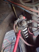
Looking at the wiring diagram that Star posted, the picture you posted and your explanation, I would be replacing the solenoid. Reason I say this is you have voltage coming from the switch, yellow wire, but the solenoid is not engaging to send voltage to the starter. Before buying a new solenoid clean the solenoid mounting and the other small terminal on the solenoid black wire and retest. If the solenoid doesn’t engage again replace.
LeakyBriggs
Member
- Joined
- Apr 26, 2023
- Threads
- 3
- Messages
- 24
How about the pedal switch? Any test to do there?
Thanks.
Thanks.
I just reread your testing post and I made a mistake. I thought you had voltage at the yellow wire attached to the solenoid which you were on the seat, brake depressed, PTO off. This would have been my third test. If doing this test resulted in 0VDC you will then have to find where you are dropping your 12 VDC. At this point a good test light is better than a meter. This can be tedious, time consuming and drive a sane person crazy. Patience is your best friend at this time. Experienced techs who understand how the different switched work have figured out how to jump or bypass different switches, but I’m not going to get into that. I’ll try to help more if you have more questions.
LeakyBriggs
Member
- Joined
- Apr 26, 2023
- Threads
- 3
- Messages
- 24
Thanks. I keep coming back to the PTO test as a way to chase the voltage loss.
Reason being is that the PTO will from the factory engage regardless of safety switches when the key is on in the "run" position. Don't have to be in the seat and don't have to press the brake/clutch/safety switch.
So if a safety switch was bad, in my head it wouldn't matter because they had no bearing on the PTO engaging.
But that may be wrong thinking....
Currently when the key is in the "run" position the PTO will not engage as it normally would.
NUMBER 1 RULE IN ELECTRICAL TROUBLESHOOTING IS NEVER ASSUME ANYTHING!!! Yes PTO switches do go bad, but unless you full understand how your PTO switch works. First, question I want to answer before testing a PTO switch is, is the starting circuit of the switch I’m working on NC or NO? The switch in Star’s diagram is NC, so current should go straight through from the RMO MODULE to the PTO switch to the pedal switch.
Tiger Small Engine
Well-Known Member
- Joined
- Dec 7, 2022
- Threads
- 1
- Messages
- 703
I have replaced 5 or 6 PTO switches this year. NC=normally closed, NO= normally open (for those not sure).NUMBER 1 RULE IN ELECTRICAL TROUBLESHOOTING IS NEVER ASSUME ANYTHING!!! Yes PTO switches do go bad, but unless you full understand how your PTO switch works. First, question I want to answer before testing a PTO switch is, is the starting circuit of the switch I’m working on NC or NO? The switch in Star’s diagram is NC, so current should go straight through from the RMO MODULE to the PTO switch to the pedal switch.
