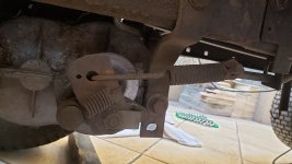
Today is brake/clutch day!

Bange

Well-Known Member
Joined
Mar 28, 2021
Threads
14
Messages
253
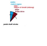
As the pedal is unique, the logic is that at the beginning of the pedal stroke, the clutch is activated/disabled and then the brake.
Separately everything works, but there is a jump when leaving and a certain delay in starting the brake, seeming that the functions are overlapping.
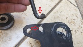
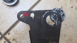
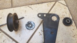
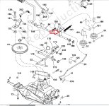
When disassembling, I could see several worn components that I believe are causing the inconvenience.
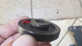
m_20230627_135058.jpg
Parece que esta peça já foi virada um dia...
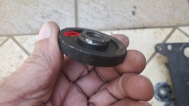
m_20230627_135042.jpg
m_20230627_143530.jpg
m_20230627_135609.jpg
m_20230627_150109.jpgpolias da tração.jpg
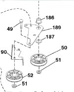
Some components are not part of the diagram but perform the same function.

The sum of these gaps and others that are difficult to photograph must be the cause.
Am I right in my reasoning or is there something else?
 

bertsmobile1

Lawn Royalty
Joined
Nov 29, 2014
Threads
64
Messages
24,705
There should be an adjustment on the rod that activates the brake which usually also has an over run spring
You back it off so that the drive cutch just starts to slip before the brake engages or dissengages .
The brake is either on or off there is no slip because it works by locking the diff so the wheels turn in opposite directions which is why it is so abruptIT is exactly the same as the P position on an automatic transmission
 

Bange

Well-Known Member
Joined
Mar 28, 2021
Threads
14
Messages
253
I only identify an adjustment in the approximation of the pads to the disc.
And it makes sense to start the brake only after disconnecting the transmission (by belt) from the gearbox.
On the pedal shaft, there is an ear with an oblong hole, which allows the brake to be activated some time (angle) after disengaging (or together?) the clutch.
Embreagem_freio.jpg
 

bertsmobile1

Lawn Royalty
Joined
Nov 29, 2014
Threads
64
Messages
24,705
Not a set of linkages I am familiar with
On all I have worked on the rod # 29 would pass strait through the brake lever a long way
Then there is a compression spring and a nut passes that so you can adjust when the rod pulls the brake lever on .
If the brake rod pushes the lever to activate the brake then the spring & adjuster nut is forward of the brake lever .
In the middle of the brake lever is a stud & nut
That moves the lever closer or further away from the pins that push on the brake pads so there is an adjustment there as well .
 
Last edited:

Bange

Well-Known Member
Joined
Mar 28, 2021
Threads
14
Messages
253
Rod #29...#26 is a spring...
But I believe that in fact there is something different that is not showing up in the diagram... I'll clear that doubt tomorrow.
 

StarTech

Lawn Royalty
Top Poster Of Month
Joined
Feb 19, 2020
Threads
79
Messages
10,274
The image of the brake rod is wrong for the style transaxle brake lever shown. The spring you are noting is on the brake caliper and is to pull it off. Also is #161 spring present and correctly connected.

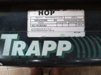
Why are you not posting the equipment model number?

I am getting so frustrating with posters asking for help but refusing to provide the info we need to even look up the equipment. Come on folks not every mower is the same setup by a long shot. Just because it is a Murray doesn't mean a lot as they were built by Murray Ohio, Husqvarna , and MTD. Some things I can gradually work it out but it takes time and some days I am too busy to done it as I got own shop problems to research...

I am to a point of just stop trying.....
 

Bange

Well-Known Member
Joined
Mar 28, 2021
Threads
14
Messages
253
Yes Sr. ...🤦‍♂️

m_20210308_173814.jpgm_20210331_130755.jpg
Motor
Model - 31P777
Type - 0602 B1
Code - 100209ZD

Did I forget something?

PS.: I just remember that my mower is frankenstein's cousin.
 

StarTech

Lawn Royalty
Top Poster Of Month
Joined
Feb 19, 2020
Threads
79
Messages
10,274
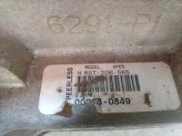
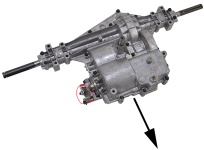
This image of the MST 206-565C showing the brake engagement lever, circled in red.
1687961696762.png


Your mower was built by Husqvarna but I not able find 960420056-03 maintenance level (-03). All I am finding is maintenance level -04. So I don't know what the changes that were made between level 03 and level 04. And Husqvarna site don't find either version. Damn I hate OEMs that hides things.

The rod should one with a thread end, spring, washer, and nylon lock nut and not what is being shown in the image of the brake/clutch system.

Sorry can't be of further help but yes the info in your post was very helpful in looking the mower and is much appreciated.
 

Bange

Well-Known Member
Joined
Mar 28, 2021
Threads
14
Messages
253
My system is...
m_20230628_115256.jpg
No threaded rod, bushing...
I think it was made during the period when employees didn't know who was going to be the boss...kkk...
The adjustment can only be made by the central screw of the brake assembly.

And don't worry... as I said before, any opinion is welcome.
 

Bange

Well-Known Member
Joined
Mar 28, 2021
Threads
14
Messages
253
Your comment about the various owners of Murray is interesting... it seems that Murray is an unwanted child, an ugly duckling that nobody wants...

So it could be that my deck (Husqvarna) originally came with the machine... and I'm blaming the previous owners.

Well, my assessment of my system can be seen in the following scheme:
Curso do pdal.jpg
As soon as I finish resolving the gaps I will confirm... or not...
 
Top