Mystery component in Z254F wiring diagram

Harbor Tom

Forum Newbie
Joined
Jul 19, 2022
Threads
1
Messages
3
While troubleshooting a no start issue with the ZT mower I was using the wiring diagram from the owners manual (bad connection at the PTO safety switch). There's a component "box" in the diagram that is not labeled and I couldn't figure out what it's function is. Perhaps some sort of relay? I've attached the whole wiring diagram and a closeup with the component circled. Any shamans on the site who might know what it is and what does it do AND where is it located? Forum search came up empty.
 

Attachments

  • wh diagram.jpg
    wh diagram.jpg
    762.7 KB · Views: 39
  • diagram closeup.jpg
    diagram closeup.jpg
    924.4 KB · Views: 29

bertsmobile1

Lawn Royalty
Joined
Nov 29, 2014
Threads
64
Messages
24,705
Parking brake switch
Plunger down completes the cranking circuit ( purple wire ) and breaks the magneto kill circuit

Most wiring diagrams seem to be done by brain dead morons who failed science & engineering and have no idea about mower wiring .
 

Harbor Tom

Forum Newbie
Joined
Jul 19, 2022
Threads
1
Messages
3
Thanks bertsmobile1. That was fast. I take it the switch is mounted somewhere at the base of one of the control arms. I'll look for it. I'll also start another thread about an engine stop problem with arms in neutral and parking brake activated.
Agreed on the poor wiring diagrams. The diagram from my post above shows nothing about connections for starter, solenoid high current contacts, charging circuit or fuel solenoid. You have to figure that out with the Kawasaki manual. Well at least the information is available.
 

ILENGINE

Lawn Royalty
Joined
May 6, 2010
Threads
39
Messages
10,035
Thanks bertsmobile1. That was fast. I take it the switch is mounted somewhere at the base of one of the control arms. I'll look for it. I'll also start another thread about an engine stop problem with arms in neutral and parking brake activated.
Agreed on the poor wiring diagrams. The diagram from my post above shows nothing about connections for starter, solenoid high current contacts, charging circuit or fuel solenoid. You have to figure that out with the Kawasaki manual. Well at least the information is available.
If the parking brake switch isn't working correctly will cause the engine stop with levers in neutral
 

StarTech

Lawn Royalty
Top Poster Of Month
Joined
Feb 19, 2020
Threads
79
Messages
10,275
There is no separate brake switch on this mower as the two motion control arms safety switches are used along with a relay. The brakes are activated when when the control arm(s) are in the outboard park position. Each control arm controls the respective arm on that side hydro unit.

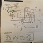
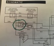
Well the component circled is a relay. Still a type switch but you won't find it shown in the IPLs but it is listed in details as PN 532109748. The IPLs will not show its location, just going have to trace the wiring harness to find it. I only got one customer with a Z254 and it hasn't been in the shop in four years. The motion control arms operates it when the arms are outboard (parked position). If either one of the motion arms switch should fail the mower will die when when in neutral non parked or forward or reverse. As depending how one of switches fail the starter solenoid (another type of relay to me) will not operate. Being a 40A relay the contacts should never get burned. But the safety takes several amps when place in park so their contacts do get burned when the ignition switch is in run position. The orange wire thru the safeties is the grounding circuit for the relay and the blue wire path is magneto kill circuit.

The solenoid next to the relay is the starter solenoid which they don't show any additional wiring for connecting to starter..
1658316727170.png
 

bertsmobile1

Lawn Royalty
Joined
Nov 29, 2014
Threads
64
Messages
24,705
I will go stand in the naughty corner
 

StarTech

Lawn Royalty
Top Poster Of Month
Joined
Feb 19, 2020
Threads
79
Messages
10,275
I will go stand in the naughty corner
Don't feel bad, its Husqvarna's lousy electrical diagram. It took me several months trying find what this was too. Even the Husqvarna support techs didn't know what it was. Somebody needs to learn how draw diagrams at Husqvarna. All they had to do was to label it.

But of course I got in a Hustler Super Z yesterday where the customer he feel air blowing out the air intake. Well what I found was the hydraulic oil cooler fan blowing across the intake and I think that is what he is feeling. Now I got to get to the real problem but I need to mow with it to diagnose the problem.

It is my first FX1000 (T100) engine that I have seen. It is a six valve engine. Appears to have two intake valves and one exhaust per cylinder. Well it least it is the carbureted version and not an EFI one so I still can wait on getting the EFI interface module for my computer.
 

ILENGINE

Lawn Royalty
Joined
May 6, 2010
Threads
39
Messages
10,035
Don't feel bad, its Husqvarna's lousy electrical diagram. It took me several months trying find what this was too. Even the Husqvarna support techs didn't know what it was. Somebody needs to learn how draw diagrams at Husqvarna. All they had to do was to label it.

But of course I got in a Hustler Super Z yesterday where the customer he feel air blowing out the air intake. Well what I found was the hydraulic oil cooler fan blowing across the intake and I think that is what he is feeling. Now I got to get to the real problem but I need to mow with it to diagnose the problem.

It is my first FX1000 (T100) engine that I have seen. It is a six valve engine. Appears to have two intake valves and one exhaust per cylinder. Well it least it is the carbureted version and not an EFI one so I still can wait on getting the EFI interface module for my computer.
Kind of like the MTD I worked on several years back that had 3 relays, and the diagram didn't show any of them. And MTD tech said they weren't used on that mower.
 

Harbor Tom

Forum Newbie
Joined
Jul 19, 2022
Threads
1
Messages
3
Thanks to everyone for your quick responses and active and positive discussion. I think I know where the relay is located. I believe it's all part of the wiring harness leading up to the run/starter switch and the PTO on/off + safety switch. There's a small black oblong cube bundled up with all the wires in that area (what I suppose you call the control panel). I thought it was just some type of connector. Now I need to go back and verify the wire colors to the "cube" to be sure.
Yes the Husqvarna wiring diagram is not much help here. I imagine a faulty relay would give someone fits trying to figure out a no start condition.
 

paul ss

Forum Newbie
Joined
Jul 21, 2023
Threads
0
Messages
1
While troubleshooting a no start issue with the ZT mower I was using the wiring diagram from the owners manual (bad connection at the PTO safety switch). There's a component "box" in the diagram that is not labeled and I couldn't figure out what it's function is. Perhaps some sort of relay? I've attached the whole wiring diagram and a closeup with the component circled. Any shamans on the site who might know what it is and what does it do AND where is it located? Forum search came up empty.
the item is a standard 12v relay and is tied to wiring under key sw. pannel. the starter solinoid is under edge of seat frame . the grds for engine ign go through safety switch circuit and will stop engine when not in correct position they also prevent starting when not in neutral and the blade solinoid is also tied between start relay and start solinoid by the blade activate button . not an easy circuit to follow .
 
Top