2013 MTD/Murray 13AN772S058 42" PTO won't engage

prometheis_78063

Forum Newbie
Joined
Jul 28, 2019
Threads
1
Messages
7
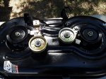
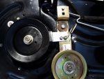
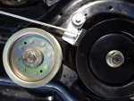
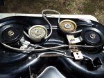
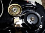
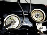
I just replaced my entire cutting deck, (2)spindles, (2)idler pulleys, brake puck/pads and brake hardware, belt and blades. When I reconnected the deck, the motor starts w/no issues, but when I engage the PTO lever on the rear right hand fender, the blades do not engage.
The old belt had slack, the new belt has less slack but still has slack. I have the shop manual (all 186 pages) and from what I've read, I have a mechanical (versus electrical) PTO engagement system. The manual shows the beltway for every deck except mine which is a "S" deck, but believe I have it threaded correctly.
After researching the web I tested the PTO switch by trying to start the engine while sitting on the machine with the PTO engaged and engine wouldn't turnover/start, but starts right up if the PTO lever is in the off position. The PTO cable is tight and in good repair. If I have to put it in the shop, I also have to pay for pickup and delivery to San Antonio 35mi away.
On a footnote there is good tension on the PTO lever. Also when I reconnected rear left and right sides of the deck I installed the "U" brackets on the deck to the outside of the pull-down lever and rod (with the cotter pin) to the inside of the mower (again no photos of the rear deck installation)

I would appreciate any inputs or suggestions you may have

700 series shop manual - http://service.mtdproducts.com/Training_Education/769_06667_700_series_riders.pdf
 

Attachments

  • full deck.jpg
    full deck.jpg
    160.4 KB · Views: 9
  • left side.jpg
    left side.jpg
    127.2 KB · Views: 8
  • right side.jpg
    right side.jpg
    133.4 KB · Views: 8

NorthBama

Well-Known Member
Joined
May 28, 2014
Threads
9
Messages
932
the deck engagement cable must pull tension on the belt to spin the blades. Check at the idler pulley pivot point that it is moving freely to tighten the belt and release the brake pads from the spindles
a picture of the way you have the belt routing would be nice
 

prometheis_78063

Forum Newbie
Joined
Jul 28, 2019
Threads
1
Messages
7
the deck engagement cable must pull tension on the belt to spin the blades. Check at the idler pulley pivot point that it is moving freely to tighten the belt and release the brake pads from the spindles
a picture of the way you have the belt routing would be nice

I have attached a drawing of the belt path provided in the owners manual (thank you mechanic mark). I have greased all pivot points and bearings in the pulleys and spindles to prevent moisture or condensation. The right side idler pulley has tension to where both brake pucks are engaged with the spindles. I can manually move the right idler pulley counterclockwise to disengage the brake pucks but when released, the pulley returns to the right most position re-engaging the pucks. Is there a belt tensioner somewhere that I'm missing? Some way to keep the pulley in the left most position? I just noticed I may have the PTO cable/spring attached to the square hole on the right pulley bracket instead of the the little round hole near the pulley pictured in figure 8.48 (attached). How can I expand the spring enough to make it fit in the hole ner the pulley? I had a heck of a time getting it where I did (in the square hole) near the brake rod!!!! I think hopefully we found the problem....will keep ya'all advised!
 

Attachments

  • Mower belt routing.pdf
    752.8 KB · Views: 6
  • IMG_20190729_0002.pdf
    1.2 MB · Views: 6
Last edited:

ILENGINE

Lawn Pro
Joined
May 6, 2010
Threads
39
Messages
9,957
Just love this design.

Park under the nearest shady spot in the yard, grab a chair, and stare at the frame and the angle of the engine to see if the front of the engine looks like it is setting lower than the rear. If so remove the front two motor mount bolts, loosen the two rear, and then insert a washer or two under each side of the front two mounting surfaces and the frame and then put everything back together.

Something about this design that allows the frame to shift and the front of the engine will drop preventing the deck belt from tightening.
 

prometheis_78063

Forum Newbie
Joined
Jul 28, 2019
Threads
1
Messages
7
I have attached a drawing of the belt path provided in the owners manual (thank you mechanic mark). I have greased all pivot points and bearings in the pulleys and spindles to prevent moisture or condensation. The right side idler pulley has tension to where both brake pucks are engaged with the spindles. I can manually move the right idler pulley counterclockwise to disengage the brake pucks but when released, the pulley returns to the right most position re-engaging the pucks. Is there a belt tensioner somewhere that I'm missing? Some way to keep the pulley in the left most position? I just noticed I may have the PTO cable/spring attached to the square hole on the right pulley bracket instead of the the little round hole near the pulley pictured in figure 8.48 (attached). How can I expand the spring enough to make it fit in the hole ner the pulley? I had a heck of a time getting it where I did (in the square hole) near the brake rod!!!! I think hopefully we found the problem....will keep ya'all advised!

Ok we're getting closer! I moved the PTO spring/cable from the square hole to under the idler pulley on the RH side brake bracket. I installed the deck and anxiously engaged the PTO blades. Unfortunately I had the deck at the lowest setting which I never use, I only use the highest setting.

The good news - the PTO engaged! yeah! for about 5 seconds

The bad news - the left side idler pulley came apart, the belt came off, luckily I was able to find all the parts. Deck now removed. Pics are provided w/the belt (see 4 attachments).

Question: I only hand tightened the idler pulleys enough so the pulleys would spin freely with some minor resistance. If I hand tighten all the way, the new pulleys do not spin freely and are seized. Which hand tightening method is correct? I really don't want to have to re-install the deck again as the PTO spring/cable is a pain to install.

btw - thanks for all your quick responses, I appreciate you!
 

Attachments

  • full deck2.jpg
    full deck2.jpg
    182.2 KB · Views: 3
  • left side2.jpg
    left side2.jpg
    113 KB · Views: 3
  • right side2.jpg
    right side2.jpg
    131.2 KB · Views: 3
  • idler pulleys.jpg
    idler pulleys.jpg
    138.5 KB · Views: 3

bertsmobile1

Lawn Royalty
Joined
Nov 29, 2014
Threads
64
Messages
24,705
Ok we're getting closer! I moved the PTO spring/cable from the square hole to under the idler pulley on the RH side brake bracket. I installed the deck and anxiously engaged the PTO blades. Unfortunately I had the deck at the lowest setting which I never use, I only use the highest setting.

The good news - the PTO engaged! yeah! for about 5 seconds

The bad news - the left side idler pulley came apart, the belt came off, luckily I was able to find all the parts. Deck now removed. Pics are provided w/the belt (see 4 attachments).

Question: I only hand tightened the idler pulleys enough so the pulleys would spin freely with some minor resistance. If I hand tighten all the way, the new pulleys do not spin freely and are seized. Which hand tightening method is correct? I really don't want to have to re-install the deck again as the PTO spring/cable is a pain to install.

btw - thanks for all your quick responses, I appreciate you!


That is wrong, you have a problem with the pulleys or their mountings.
A idler should spin freely no matter how tight you do the mountings up because the bolt/nut should only bear on the inside race and you got to put a lot of tons of pressure on them to distort them.
You probably have a washer where it should not be that is bridging the inner & outer races or one of the spacers is on the wrong side of the pulley or the pulley is up side down.
The inner race is usually around 0.010" wider than the outer race so when tightened only the inner race is clamped.
If there is a spacer inside the pulley it should have a shoulder for the inner race to bear against so that the outer race & pulley can spin freely.
Washers that go under pulley mounting bolts are high tensile and thicker than a normal washer so they don't distort and foul on either the balls or the outer race.
 

prometheis_78063

Forum Newbie
Joined
Jul 28, 2019
Threads
1
Messages
7
That is wrong, you have a problem with the pulleys or their mountings.
A idler should spin freely no matter how tight you do the mountings up because the bolt/nut should only bear on the inside race and you got to put a lot of tons of pressure on them to distort them.
You probably have a washer where it should not be that is bridging the inner & outer races or one of the spacers is on the wrong side of the pulley or the pulley is up side down.
The inner race is usually around 0.010" wider than the outer race so when tightened only the inner race is clamped.
If there is a spacer inside the pulley it should have a shoulder for the inner race to bear against so that the outer race & pulley can spin freely.
Washers that go under pulley mounting bolts are high tensile and thicker than a normal washer so they don't distort and foul on either the balls or the outer race.

ok. The pulley is flat on one side where the cap goes on top, then the nut(#16, 24, 48, 32 and 54). On the bottom the fitting has a bolt, belt guide, a washer and then extrusion/longer fitting (ref link) on the pulley.

https://www.partstree.com/models/13an772s058-murray-lawn-tractor-2013/mower-deck-8/

Should the extrusion/longer side be on top? The cap would not seat correctly if that were the case, right? I think I have them on correctly and have re-used the same washers, brackets and springs. Maybe the washer goes on top of the pulley and underneath the cap; not under the pulley and on top of the belt guide as pictured? thoughts?
 

bertsmobile1

Lawn Royalty
Joined
Nov 29, 2014
Threads
64
Messages
24,705
The stand off bush / boss that goes into the pulley should have a shoulder on it
When pressed into the bearing it should be just short of being level with the inner race.
Thus the protection cap should push the inner race down onto the bush when you tighten the bolt.
Generally the shoulder side goes down so it holds the pulley clear of the deck / tension arm.
IT was easy when the parts were new because they came with the bushing already fitted so it could not be fitted upside down.
However now days it is cheaper to sell a generic plain pulley with a loose bush in a bag
This is what the original pulley looked like , however it is upside down.
https://www.stens.com/280-646-flat-idler
Although it shows a double row ball bearing with a custom extended inner race , they have not been used for decades and all the idlers use a standard single row deep groove bearing, with a bush.
The latter is about 1/4 the price of making the double row set up because std bearings and a lot cheaper.
 

prometheis_78063

Forum Newbie
Joined
Jul 28, 2019
Threads
1
Messages
7
The stand off bush / boss that goes into the pulley should have a shoulder on it
When pressed into the bearing it should be just short of being level with the inner race.
Thus the protection cap should push the inner race down onto the bush when you tighten the bolt.
Generally the shoulder side goes down so it holds the pulley clear of the deck / tension arm.
IT was easy when the parts were new because they came with the bushing already fitted so it could not be fitted upside down.
However now days it is cheaper to sell a generic plain pulley with a loose bush in a bag
This is what the original pulley looked like , however it is upside down.
https://www.stens.com/280-646-flat-idler
Although it shows a double row ball bearing with a custom extended inner race , they have not been used for decades and all the idlers use a standard single row deep groove bearing, with a bush.
The latter is about 1/4 the price of making the double row set up because std bearings and a lot cheaper.

I flipped the pulley down side up with the same result. I returned the pulley to the original upright position (flat side up) and moved the washer from under the pulley (as described in the parts diagram link above) to the the top of the pulley between the the pulley and the cap. It worked! I could tighten it down and still have the pulley spin freely! The unit is now back together, tested and cutting like a champ (but now I have to cut my grass)!

Seems I may have to re-level the side to side adjustment screw (pg 22 in the owners manual) as the left side is 1/2" higher than the right. I'll wait until I cut the grass to see for sure.........until next time, thank you all!
 
Top