Regulator/Rectifier Test

Adsila Sinewa

Member
Joined
May 1, 2019
Threads
3
Messages
10
I recently purchased a new regulator/rectifier for my 23 hp Kohler engine (12/15A part# 25 403 35-S)

Before installing the regulator/rectifier and replacing the Blower Housing, I decided to first test the voltage regulator to make certain that it was going to output the required 12+ volts. I did this by the following test.

1. I hooked up my multimeter to the rectifier-regulator plug A/C terminals and ran the engine at 3600 RPM which displayed 43 volts AC. (I've read that I should have at least 28 volts AC. Could the regulator be putting out too much A/C?)
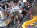
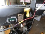
2. I then attached the rectifier-regulator to the engine making certain that it was well grounded. See attached photo.
3. I then connected a red wire from one (out-) side of the rectifier-regulator plug to one side of the A/C terminal of the rectifier-regulator. See attached photo.
4. I then connected a black wire from the other (out-) side of the rectifier-regulator plug to the other outside A/C terminal.
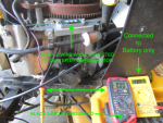
5. Next, I switched my multimeter to DC and placed the red lead to the middle B+ terminal and touched the black lead to the engine (in several spots). However, I only got a reading of .02 Volts DC.

Could you tell me what I’m doing wrong in my test? The regulator/rectifier was a new original Kohler item.

I went ahead and attempted to fully install the regulator/rectifier, but the battery did not indicate that it was charging.

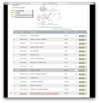
In placing the order I used the information derived from kohlerenginesparts.com. See the attached screenshot:

I purchased this engine new in late 2016, but I discovered late last fall that the voltage regulator tested defective. Although I have a new high quality battery and the engine starts without a problem, obviously I need a working voltage regulator.

Any assistance you can give me will be greatly appreciated.
 

Attachments

  • volt reg test.JPG
    volt reg test.JPG
    131.2 KB · Views: 26
  • kohlerengineparts.png
    kohlerengineparts.png
    401.1 KB · Views: 20

ILENGINE

Lawn Pro
Joined
May 6, 2010
Threads
39
Messages
9,957
I didn't see during your testing that you actually applied 12v to the B+ center lead of the regulator. I see where you connected it to the battery fully installed, but do we know that you have 12 volts to the center terminal on the regulator. No battery voltage at the center lead of the regulator and it won't close the trigger to allow charging.
 

bertsmobile1

Lawn Royalty
Joined
Nov 29, 2014
Threads
64
Messages
24,705
Unless the rectifier is bolted down, the ground will not be good enough.
Sitting on the control bracket is just not good enough.
When you refitted the rectifier did you put the ground strap back on ?
Usually what happens is the ground strap cracks through then it arcs at the fracture point and the high current burns out the diodes in the rectifier.

When I replace them I put a ground wire between both of the rectifier mounting bolts and a blower housing bolt on either side so they are independent .
with the engine running back probe the purple wire to ground it should read higher than battery voltage.
If the rectifier is also a regulator the voltage read at the purple terminal will vary with the state of battery charge.
I like to start the engine then remove the + battery terminal .
If the regulator is working then engine will remain running
If it is not working then the engine stops because the fuel solenoid shuts down.
Then to really test the system I turn the PTO on.
People also forget that energy is watts (V x A ) and you can get a good voltage reading but no current.

Let us know what you have found.
 

Adsila Sinewa

Member
Joined
May 1, 2019
Threads
3
Messages
10
Thank you Bertsmobile1,

ILENGINE,

Again, thank you for your prompt response. I was unable to work on my project yesterday. Your statement of <<do we know that you have 12 volts to the center terminal on the regulator? No battery voltage at the center lead of the regulator and it won't close the trigger to allow charging>> was new knowledge for me. That led me to searching YouTube. I found the following test at https://www.youtube.com/watch?v=sb1bVmnIqHk.

The fellow suggested hooking up one multimeter to the battery only, then using a second multimeter to connect the positive lead to the wire that connects to the B+ terminal of the voltage regulator AND the black lead to ground. Then turning on the key to make certain that there is voltage going from the battery to the voltage regulator. I did this and I got ZERO. Do you think that my key switch module could be bad? Is there a test for this?

I have a parts manual for my Cub Cadet, Model SLT1554 and the part number for a key switch module is 725-04227. However, keep in mind I replaced the damaged (original) 27 HP Command engine with a new 23 HP Courage engine, and I am not certain that the key switch for the Command engine will work with the Courage engine. Also, I found a key switch module that appears to be a basic unit for 1/3 of the price of the factory original equipment. Will the cheaper unit work?$12.49 switch.jpg

Below is a picture of the cheap key switch, the factory original switch and my test setup.

At last I believe that I have isolated my problem,… now I have to solve it.
 

Attachments

  • $31.50 switch.png
    $31.50 switch.png
    817.5 KB · Views: 15
  • test for voltage.png
    test for voltage.png
    649.2 KB · Views: 15

Adsila Sinewa

Member
Joined
May 1, 2019
Threads
3
Messages
10
SUCCESS at last!!!

ILENGINE, I found THE solution in your post to clarkman5000 in Jul 2018 when you explained that <<the purple wire can be wired directly to battery which is the recommended Kohler method anyway>>. Like clarkman5000, I thought that the 12V on the B+ terminal of the regulator was a one-way out phenomenon. Also helpful was the point that <<It will not discharge the battery>>.

bertsmobile1, I took your advise and spliced in a fuse between the B+ terminal and the positive side of the battery. Also, I made <<two grounding straps and ground the rectifier on both sides to different grounding points.>>

Without going into a lot of detail, I’m convinced that my key switch is bad. I plan to replace it eventually; meanwhile, I can use the $31.50 on another project.

As you can see I decided to cut a hole in the blower housing and mount the voltage regulator/rectifier on the outside, thereby eliminating the need to remove the blower housing, if and when I need any future work on the regulator/rectifier. See attached pictures. Later today I plan to cover the terminals with masking tape to keep out the dirt. By the way, the original regulator/rectifier proved to be a good unit.

Again, thanks to all that helped me solve my problem. Maybe this post will help someone else with the same issue.
 

Attachments

  • hole in housing.JPG
    hole in housing.JPG
    123 KB · Views: 13
  • finished job.JPG
    finished job.JPG
    143.3 KB · Views: 17

ILENGINE

Lawn Pro
Joined
May 6, 2010
Threads
39
Messages
9,957
I fought a similar issue last year that you were having. In my case I had correct output from the stator, a know good regulator/rectifier, and even tried a different regulator to be sure. had 12 volts at the regulator but wouldn't charge the battery Found that I had 12 volts when tested with a multimeter, but if you put a small load on the wire like a 12 volt test light the voltage at the regulator would drop to 3 volts. Bypassed key switch, and amp gauge and went straight to battery but it would show 13.5 at the battery when running. Charge gauge would show discharge when deck engaged but battery was charging so not worth tracking down bad wire connection due to budget constraints.
 

Adsila Sinewa

Member
Joined
May 1, 2019
Threads
3
Messages
10
ILENGINE,

Thanks again for the idea of testing at the battery AND testing under load (blades engaged). Everything is copacetic! 14 volts.
 
Top