First a little computer magic
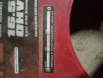
Go back and drag the mower out into the sunlight.
Take some photos of tag at the highest resolution you camera has ( camera is better than a phone ) at different angles.
Go inside and upload the images then play around with the contrast also try inverting the colours as well.
Digital cameras are a lot more sensitive to dirty white on dirty white than your eyes,
The area under where the type was will be less faded than the areas without the type so will be closer to the original colour.
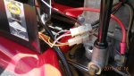
Next , most Murrays are wired according to the std Briggs wiring diagrams.
The wiring schmatics were done by a keyboard jockey with absolutely no idea of what he was doing
But they should be good enough for you to blunder through with.
Later models will have what passes for a wiring diagram will be found in the owners manuals that have a parts section in the back.
Below are a couple from Murray books and the general Briggs wiring diagram
This is a diatribe from some previous answers to people with wiring / stating problems.
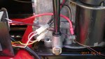
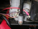
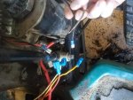
Before you do any wiring repairs , remove the blower housing and remove the kill wire form the magneto.
After you have finished check this wire for voltage with every combination of the controls.
If it even thinks it is going to get battery or alternator voltage then control chip in the coil will self destruct and those little buggers are not cheap.
Behind the ignition switch are tiny letters nd they code out like this
B = battery voltage always active
S= Start, gets 12 V when turned to the start position
A = Alternator gets connected to B so the battery can be recharged
L = Lights may be a 12 V teminal with DC lights or ground for AC lights.
M = Magneto should be either open circuit or ground when turned off
G = Ground.
There might be A1 & A2 or L1 & L2 and these just split circuits for things like hour meters , accessory power outlets , hour meters & grounding the alternator to effectively make it a brake when the engine is shut down.
The PTO & brake switches are usually double switches.
One side is live and used for cranking and the other side is ground, used for safety switching.
The switches connect the terminal flat side to flat side ( orange to orange or yellow to yellow )
The PTO & BRAKE switches will have one side connected pin in & the other side disconnected pin in and these reverse when the pin is out.
If you have to replace them make sure the new switches work the same way as JD use an identical looking switch where the contacts are reversed.
The start circuit is a loop,
Fuse > B terminal >S terminal > PTO Switch > brake Switch > solenoid trigger > ground.
View attachment Murray wiring -1.pdfView attachment wiring -2.pdf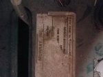


.JPG")
.jpg")
.jpg")
.PNG")