Electric PTO will not engage?

BashRipRock

Member
Joined
May 7, 2018
Threads
7
Messages
31
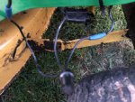
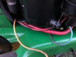
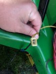
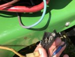
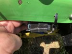
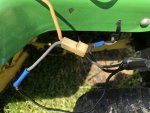
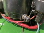
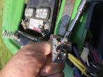
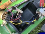
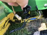
I recently inherited an STX 38 Yellow Deck Lawn Mower. The machine looks very clean. The engine is a 12.5hp Kohler. It's a 5-speed transmission. It runs great, except the electric PTO will not engage. Once I received the mower I drove it around the yard. Everything seemed fine until I switched on the electric PTO. It sounds like it wants to engage but it will not. The original PTO switch was severally corroded. I cleaned up all the wire ends and replaced the switch with a brand new one. It still will not engage. I got to looking today and found a wiring nightmare on the right side of the mower, near the large grounding plug, if you are sitting in the seat. There is a very heavy black cable attached to the frame in the same general vicinity. I'm sure that is the ground. I have a yellow wire with a small two male round prong clip. Then I have a small black wire coming from the large grounding point to a wire nut that has another black wire going back to the yellow wire with the small two prong plug. Then the third black wire tied with the other two then goes straight to an odd looking connector that has 1 spade going one way and the other spade going another. So one horizontal and one vertical. This connector end plugs directly into the female end that is attached to the electric PTO. I'm guessing this the area of concern but I am not 100% sure. The Tech Manual I have for the mower shows the Yellow Wire and the Purple Wire going to the electric PTO. I have a yellow wire but it has a small 2 round prong end on it with a black wire going into it. I'm not finding a purple wire in that area. But, I remember a purple wire on the new electric PTO switch. Everything else is top notch from what I can tell. New spindles on the deck. I installed a new deck belt yesterday. Yes, I hooked the PTO belt back up properly. Looking for suggestions, thoughts, advice, perspective or anything else anyone has to add. I sure appreciate it. Thanks in advance.
 

Rivets

Lawn Royalty
Joined
Mar 11, 2012
Threads
55
Messages
14,758
You need to give us more info before we can help you as wire colors mean very little on older units. We need to know: Make, more than yellow deck. Model and serial numbers, so we can see if there is a wiring diagram. Your electrical skills and understanding, so we know what terminology to use. Do you understand solenoid, NO safety switch, NC safety switch, relay, wiring diagram. Electrical troubleshooting can be a real pain, especially if you lack good electrical skills, so please help us help you by painting a picture of what you are looking at. Such as, if you have a diagram the red wire goes from the large terminal on the solenoid to the B terminal on the key switch. A diagram will tell you which component each wire should go to and if there are any junctions in between. Waiting to hear back.
 

bertsmobile1

Lawn Royalty
Joined
Nov 29, 2014
Threads
64
Messages
24,705
If you have the JD technical manual for the STX then you can not do any better.
IT would appear that electricity is taught as badly in USA schools as it is down here thus it confuses 99% of the population.
This includes a lot of both professional & home mechanics who do all sorts of butchery to cars trucks motorcycles & lawn mowers.

The good thing is the JD manual shows you where to test a plug or switch as well as the colours of the wires that should have been there.

The PTO switch acts as a switchboard for most of the kill wire circuits, thus all of the black wires.
Check your wiring diagram and you should have a blue wire coming out of the PTO switch which should be the switches 12 V for the PTO,

Check the PTO clutch by jumping that wire to the battery +
If that does not work then jump the - wire as well.
If that does not work then your PTO clutch is faulty, out of adjustment or has broken wires.

Get back when you have done the testing.
 

BashRipRock

Member
Joined
May 7, 2018
Threads
7
Messages
31
I apologize for the lack of information. This was my first post on here. I am used to the Truck Forums where some information is just implied. This is a John Deere STX 38 with the Yellow Deck (the newer generation of this model had a black deck) headlight package was optional on this model and mine does NOT have headlights. Serial#(Product ID Number) MOOSTXB611787, it has a 38" deck. My level of understanding electric components and terminology would be above moderate/average but not expert. I understand wiring diagrams and use a Volt Meter on a daily basis. I finally had a chance to scan the Technical Manual to find the exact diagram I believe I need. It looks like someone has done less than a quality job on this "wiring" job. I checked my notes versus the Technical Manual I have the correct wires at the Ignition Switch and going to the PTO Switch. I need to open this back up to verify I have the correct wires leaving the corresponding switches. It is currently 10pm here in Ohio so I won't be able to do any Voltage checks/tests until tomorrow. I will let you guys know what I find out. Thanks for the information.
 

Attachments

  • 3 Black Wires and Clutch Connection.jpg
    3 Black Wires and Clutch Connection.jpg
    20.9 KB · Views: 8
  • Serial Number Tag.jpg
    Serial Number Tag.jpg
    10.3 KB · Views: 3
  • Visual Pic.jpg
    Visual Pic.jpg
    12.9 KB · Views: 5
  • Yellow Wire 2 Prong.jpg
    Yellow Wire 2 Prong.jpg
    8.4 KB · Views: 4

BashRipRock

Member
Joined
May 7, 2018
Threads
7
Messages
31
Well, I guess I should have stayed in bed today! In response to Rivets and bertsmobile1. Here comes the information.

I have already installed a new PTO Switch. (the original was corroded and not operational) Battery Terminals have been cleaned and I have a good solid connection.
I tested via the John Deere Technical Manual 4-56,4-57,4-58,4-59 (3/21/97)

1. Battery Voltage with Ignition Switch on and PTO Switch on - 11.77 Volts (in the manual normal operating range is 11.8-13.2 volts)
2. Key Switch terminal A on testing "400" Yellow Wire - 11.66 Volts
3. Key Switch terminal B on testing "200" Red Wire - 11.71 Volts
4. PTO Switch on testing "400" Yellow Wire - 11.57 Volts
5. PTO Switch on testing "750" Blue Wire - 11.52 Volts
6. At the PTO Clutch Connector with Ignition and PTO Switch on "750" Blue wire - 12.37 Volts
7. Across the terminals at the PTO Clutch Resistance measured 3.5 ohms (in the manual normal operating range is between 3-10 ohm)
8. PTO Clutch "125" Black wire resistance measured .0-.1 ohm (in the manual Maximum is .1 ohm) (in the manual it also states "If Not Normal" Check PTO clutch "125" black wire engine ground circuit, and battery negative cable ground connection) I did this and showed 0 ohms.
9. The fusible link is good I pulled the fuse. Now in the pictures, the fusible link is connected to a Purple Wire with Black Stripe. That is not on the PTO Circuit Diagnosis Section that I have.
10. There is a Purple wire that comes out of the PTO Switch.
11. I know this wire looks faded in the picture but the Purple Wire with Black Stripe goes to the Starter Solenoid. Along with the Red Wire.
12. I took a picture of the PTO Clutch Connector. Several different looks. Is that the correct connector?

Now with it whisper quiet in my backyard this afternoon, when I switched the Ignition Switch on and then the PTO Switched to on I heard the "PTO Clutch Noise" or clap, whatever we all can agree on. Still scratching my head, I started the tractor it was running fine. I switched the PTO Switch On and once again it acted like it wanted to but nothing happened. So, I shut it down and came in here to post all the info I had. I have the complete manual so I can look at other diagrams. It's about 360 Pages so I would need a starting point. Thanks in advance for any and all assistance. bertsmobile 1 you are correct, they "teach" "us" just how to get it going method here in the United States. Then guys like us are left to "Fix it Right"! On a side note, I would love to visit Australia someday! It's on the bucket list, but that 17-hour flight might be a deal breaker.
 

Attachments

  • IMG_0023.jpg
    IMG_0023.jpg
    83.8 KB · Views: 2
  • IMG_0022.jpg
    IMG_0022.jpg
    75.9 KB · Views: 2
  • IMG_0021.jpg
    IMG_0021.jpg
    106.2 KB · Views: 2
  • IMG_0020.jpg
    IMG_0020.jpg
    97.7 KB · Views: 2
  • IMG_0019.jpg
    IMG_0019.jpg
    99.4 KB · Views: 4
  • IMG_0018.jpg
    IMG_0018.jpg
    142.2 KB · Views: 2
  • IMG_0024.jpg
    IMG_0024.jpg
    135.3 KB · Views: 2

EngineMan

Lawn Addict
Joined
Jun 12, 2012
Threads
9
Messages
2,275
By the time I had done all that you have I would taken off the clutch and tested it first, that way you would know that the clutch is working or not, before going into wiring and switchers.
 

BashRipRock

Member
Joined
May 7, 2018
Threads
7
Messages
31
EngineMan - Thank you. Fortunately or unfortunately depending on your perspective, I have nothing but time!
 

Luffydog

Well-Known Member
Joined
Jan 31, 2018
Threads
6
Messages
566
Possible the air gap on the clutch. Have you checked to see if the spindles turn free when belt is off.
 

BashRipRock

Member
Joined
May 7, 2018
Threads
7
Messages
31
Luffydog I can't say I even thought of that. Thank you! I will check it out tomorrow sometime.
 

NorthBama

Well-Known Member
Joined
May 28, 2014
Threads
9
Messages
932
i agree with engineman i think you should take the clutch off check air gap apply voltage and also check bearings
 
Top