LT160 replacement wiring connector

Cannon51

Active Member
Joined
Apr 21, 2013
Threads
5
Messages
53
I mowed my sons grass Wed with the Lt160 and occasionally it would bog down and start missing. I could cut the blades off for a few seconds and reengage (manual PTO) them and keep mowing. Today I was mowing my grass and every time I turned the blades on it would start missing. I first thought it was fuel so I cleaned the bowl out and removed the rubber tip from the solenoid. No change. Then I decided it might be electrical so I unplugged the engine and chassis wiring harnesses. It was warped in 3 or 4 rounds of tape and one connector has apparently been hot and melted some of the connector. With the connector unplugged it ran fine and I mowed about 15 more minutes and plugged it back together, it never missed again. I don't want to keep using it like this until I figure out why the second terminal down got so hot. Near as I can tell the Top-white wire is coil ground, the second-white wire is AC to something, the third-black is DC and the bottom-brown is also AC. I need a LT160 wiring diagram to confirm before I start trying to repair/replace this connector. As of now it's running fine put back like it was except for the rubber tip on the backfire solenoid. I can't find this connector online anywhere, Should I just abandon it and splice in another connector?LT160 001.jpg
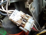
Cannon
 

bertsmobile1

Lawn Royalty
Joined
Nov 29, 2014
Threads
64
Messages
24,705
AFAIK that connector is fairly well unique to JD.
It is not listed as a replacement part other than as part of a loom.
Conside smashing the plastic bits, cutting off the terminals and replacing them with a STD 4 way blade plug

You can quite hapily run the mower with that plug disconnected only down side will be the battery will eventually go flat and none of the engine cut outs will work

This is the relevent bi from the 133-155 manual.
Not quite the same but JD was consistant with their colour coding so it should help
View attachment LT133_LT155_LT166_.pdf
 

Cannon51

Active Member
Joined
Apr 21, 2013
Threads
5
Messages
53
Thanks for the diagram, I think for now I will route the burned wire outside the OE connector. That will isolate it from the others and I can monitor how hot it gets. Looks like the burned wire goes to a "Shunt Relay" which I am not sure what is. I hope it just had a poor connection and built up heat rather than was drawing to much current.
Cannon
 

motoman

Lawn Addict
Joined
Aug 11, 2011
Threads
65
Messages
2,566
Or perhaps...classic use of a DVM look at current flowing in that white wire. Instead of guessing and feeling for overheat you could compare the current with the max expected in that gauge wire. If useful I can dig out the quick check stranding guide to id the white ga wire. You would have to strip it to count the strands as od is not accurate due to varying insulation material thicknesses.
 

Cannon51

Active Member
Joined
Apr 21, 2013
Threads
5
Messages
53
I routed the second wire down outside the OE connector. I did hold the bare spade connector while cranking and running and did not feel any heat. I did check the second and forth wires for voltage and got 16VAC from the wire to ground on both of them. I've seen a single AC wire go to to the chassis harness for AC lighting but never two. Since it will crank and run without the engine harness connected I'm not sure what the "Shunt Relay" I believe these wires feed accomplishes. I'm going to try it this way and see if the stalling comes back, I believe that's a separate problem. It's rained almost every day lately in North GA, I hope it just a wet connection in one of the safeties.
Thanks
Cannon
 

bertsmobile1

Lawn Royalty
Joined
Nov 29, 2014
Threads
64
Messages
24,705
The 2 AC wires go to a real full wave rectifier.
JD put proper rectifiers on every thing other then the bottom line 100 series.
Every thing else is proper DC
 
Top