Export thread

Ariens EZR 1742 Wiring Problem

#1

T

trukman1

I purchased athis mower from neighbor who bought it from a friend that has history of screwing things up. He cut the PTO switch and installed a toggle switch. Problem is, I purchased new PTO switch and when I opened it up he'd cut all the connectors and wiring. There two purple wires and two black wires going to a plug that he jumpered to the toggle switch (Just off the purple wires.). I also can't figure out which side of the new switch the wires go to. One side has three COM markings and the other A B C. If I could find where the brown and yellow wire goes I'd know which side gets wired accordingly but am at a loss as to the purple and blacks that he put to the toggle switch. I hope this makes sense. Any help will be greatly appreciated. Thanks in advance for any help.

BTW: I'm a paraplegic and just bought this cause his wife was on her last nerve. I can't get on it but my other neighbor cuts my grass for me and was excited about getting it thinking it would be more fun to mow with. I don't want to let him down. Ole' softy I guess.


#2

B

bertsmobile1

Firstly lets check you got the correct switch
According to the parts book your should have Ariens part # 01545600
This is a Delta switch with 5 terminals
The terminals may have tiny numbers cast into the back of the switch
Below is the connections
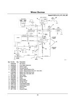
and under that the wiring diagram
Both of which are a free download from the Ariens web page   Pinout.jpg
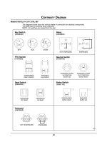
  wiring.jpg
Just beware that people rarely chop off plugs & insert a toggle switch because the switch itself is bad
Usually it is because other switches ( or relays ) are bad and they are too bone lazy to work through the problem .
I would suggest pitting female terminals on the PTO wires then making some short jumpers with 2 male terminals
Then you can use these to bypass the lap bar switches, relays seat switch etc
As you can see , all switches are power switches unlike normal practice to make them ground switching which reduces the number of places where you can get a short circuit to the frame blowing fuses
If you have trouble with the wiring diagram ( which would get a B- in one of my classes ) then get back & we can work through it with you


#3

T

trukman1

Bertsmobile1, Thanks for the schematics and switch details. Been raining and I have to work on it outside laying on the ground so when it dries up I'll get on it. Thanks again!


#4

B

bertsmobile1

When ever you have time, noting is compulsory
While it is raining work through the wiring diagram
There is a mistake on the key switch as the red (Battery ) wire has to be connected to A in both the on & start positions so the ibottom 2 o"s should be shown as tied or there would be no power to the motor the G (Ground ) and M (Magneto ) connections are depicted correctly as the various safety switches as supposed to work in parallel with the key sot they can over ride the key to shut the engine off .
I might suggest removing the blower housing and disconnecting the kill wire from the magneto lest you accidentally send power to the magneto which will kill it stone dead .


#5

T

trukman1

Thanks. I spent time going over the info you sent me. I used to do wiring for control panels in the shop (30 years ago) and it all made sense to me when I got to see it. Double thanks for the caution about the magneto!! Gary


#6

B

bertsmobile1

Excellent
You need to appreciate we have to assume you know nothing until otherwise informed.
Should be a doddle for you then.
You would not believe how many people "test" their coils by flashing the battery + wire across the kill terminal.
I have seem at least a dozen You Tube videos advising people to do just that
Normally it is not a problem because most safetys are ground circuits, however some relay heavy circuits switch on the + side instead and the hall effect chip responds to negative voltages in the micro volt range


Top