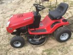
Snapper RER 28085S Restore

mattm55

Active Member
Joined
Mar 6, 2017
Threads
3
Messages
81
Ahhh decisions, decisions, decisions...... Ya know matt , sometimes it's a good thing to just set a chair a ways back from your project ... open a cold one and RELAX ... take a break ... and marvel at what you have accomplished thus far !!
Then you can visualize what if ...??? I do this ..THAT way ..YEAH go ahead ... YOU deserve it ... and there's always tomorrow . ..:biggrin:

Yes, I have done that on many occasions. Sometimes sleeping on it helps clear your mind and offers betters ways of solving a problem. I keep telling myself, over and over, it's just a lawnmower. The first cut of the season will take that newness out of it pronto. And I do hear the grass waking up from a cold winters nap (upstate NY) so time is running short. "TSSST".

"TSSST - ...the sound of a beer can opening/a vocal attempt to reenact the sound of a beer can opening." ;o)
 

Boobala

Lawn Pro
Joined
Feb 15, 2015
Threads
200
Messages
7,000
Yes, I have done that on many occasions. Sometimes sleeping on it helps clear your mind and offers betters ways of solving a problem. I keep telling myself, over and over, it's just a lawnmower. The first cut of the season will take that newness out of it pronto. And I do hear the grass waking up from a cold winters nap (upstate NY) so time is running short. "TSSST".

"TSSST - ...the sound of a beer can opening/a vocal attempt to reenact the sound of a beer can opening." ;o)

I get it... you enjoy my friend ....ENJOY !!!
 

mattm55

Active Member
Joined
Mar 6, 2017
Threads
3
Messages
81
Thanks for others who have done the Briggs to Honda repower...

The throttle hookup from the Briggs to Honda needs to be modified. The original Briggs cable is about 14" long as shown in the image below.

briggsThrottle.jpg

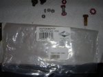
The cable attached to the Briggs engine horizontally where the Honda will be located vertically. I ordered Part#7075089YP which is the Honda throttle cable. This cable is about 39" long.

hondaThrottlePart.jpg

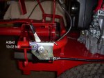
Since the mount on the Honda throttle cable was top mounted with 2 screws I decided to take my original throttle handle (side mount) and remove the short cable (straighten z-bend) and replace with the longer 39" cable and bending the z-bend. That way I have my original side mount but with a longer cable. You could just find the longer cable instead of buying the handle and save $. I also added another 10x32 screw in my handle to make it more secure and not want to rotate as the Honda's extended travel is tighter and caused the handle to move.

hondaThrottleMount1.jpg

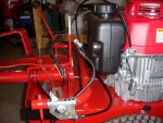
For the routing of the cable I initially had it looping on the outside but decided to reroute the cable towrds the tank indent so it wouldn't be caught on anything and pull out.

DSCN2799.jpg

DSCN2803.jpg

Matt
 

mattm55

Active Member
Joined
Mar 6, 2017
Threads
3
Messages
81
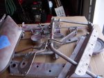
I think I missed showing the rebuild of the front end. All new bushings, keys and greased. Took the slop out of the steering by adding some extra washers behind the tie rods.

DSCN2789.jpg

Matt
 

mattm55

Active Member
Joined
Mar 6, 2017
Threads
3
Messages
81
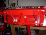
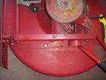
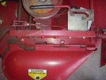
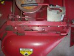
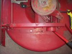
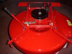
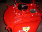
I'm starting on the electrical wiring and in parallel I wanted to start on the 2nd phase of the build. The cutting deck needs to be disassembled, cleaned, painted and reassembled.

deckRef1.jpg

deckRef3.jpg

*An impact gun definitely helps with disassembly of the main pulley nut and the blade bar nut. These are on there quite tight. The blade bar is also threaded on so once you remove the nut you need to unscrew the blade bar. My spindle bearings are in good shape so I won't be replacing those.

DSCN2814.jpg

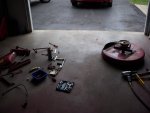
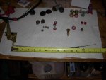
A pile of bead blasted parts ready for primer and paint. The deck I'll have to do by hand as that is the only part that won't fit into my cabinet.

DSCN2815.jpg

Matt
 

Boobala

Lawn Pro
Joined
Feb 15, 2015
Threads
200
Messages
7,000
Ran across these pics ...thought you might enjoy....

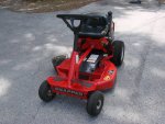
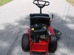
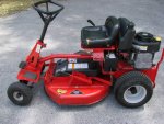
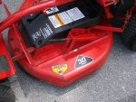
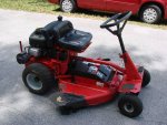
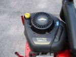
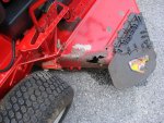
00G0G_485JEs7Svlb_1200x900.jpg...00N0N_e8tRbip9Jte_1200x900.jpg...00S0S_7ZuXD5zJhmO_1200x900.jpg

...00u0u_7g5oGxGedyu_1200x900.jpg...00z0z_dY4DKqOCEeE_1200x900.jpg

00202_ip178HzxGtH_1200x900.jpg...00404_1RThasO6qtp_1200x900.jpg

Got one of my murray pics in there somehow.. cant delete it ..SORRY !!
 

Attachments

  • 00T0T_4o9JU3QegxH_1200x900.jpg
    00T0T_4o9JU3QegxH_1200x900.jpg
    119.4 KB · Views: 7

mattm55

Active Member
Joined
Mar 6, 2017
Threads
3
Messages
81
Ran across these pics ...thought you might enjoy....

View attachment 31650...View attachment 31651...View attachment 31652

...View attachment 31654...View attachment 31655

View attachment 31656...View attachment 31657

Got one of my murray pics in there somehow.. cant delete it ..SORRY !!

Thanks for sharing. I like the way they (Snapper) updated the cutting height bar on yours. The one I have takes a good amount of effort to raise and lower. I also like the cup holder location. I asked my wife where she wanted it located (she rides while I push) and she said up on the steering. I may offer her that location even though we have the second pedal.

Thanks.
 

mattm55

Active Member
Joined
Mar 6, 2017
Threads
3
Messages
81
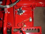
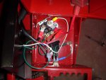
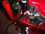
While waiting for the paint to dry on the deck and deck parts I started working on the electrical wiring of the Snapper. I decided to eliminate the interlock for the cutting deck but kept the interlock for the Park safety switch. It's more likely to try to start in gear than have a start situation with the blade moving.

One other thing is that I am removing the "push button" start and replacing it with a key start so I won't have to reach back and push that button.

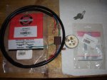
Parts List:
  1. Wiring Harness: 7074062YP
  2. Ignition Switch (4 pole): 7073997YP
  3. Wire: 16AWG different colors or tape, 6AWG (red & black) for load to battery off solenoid
  4. Connectors: 16AWG & 6AWG
  5. Solenoid (4 pole): A generic solenoid with 3 or 4 poles from AMZ for $10.
  6. In-line Fuse: 10 amp in-line fuse block

electricalParts1.jpg

electricalSolenoid1.jpg

I found that the pre-built wiring harness made an easy job as it connects directly to the ignition switch with the ground wire included. This routes thru the tube and has enough wire to make it to the "electrical junction box" area.

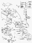
Since there seems to be very little on the wiring layout on the internet I will do a simple diagram of how I wired mine up with images to come. I am using this schematic as a good starting reference.

electrical1.gif

Thanks, Matt
 
Last edited:

mattm55

Active Member
Joined
Mar 6, 2017
Threads
3
Messages
81
Here is a simple wiring diagram for the Snapper Honda GXV-390 repower.

electricalDiagramSimple1.jpg

1. In my haste I didn't realize the Honda already had a solenoid next to the starter. I already had a generic solenoid mounted and decided to use mine, In the case it ever goes bad, I'll switch over to the Honda's. So in my diagram I only used the Honda's solenoid lug that went to the starter.

2. In my diagram I did not show the inline 10 A fuse on the Battery side of my solenoid. If you need me to draw or explain, just send me an email. It's pretty simple to add.

DSCN2818.jpg

DSCN2820.jpg

Matt
 

mattm55

Active Member
Joined
Mar 6, 2017
Threads
3
Messages
81
The deck is complete and ready to be mounted.

Before :
deckRef3.jpg

deckRef1.jpg

After:
completeDeck1.jpg

completeDeck2.jpg

Matt ;o)
 
Last edited:
Top