Getting Slop Out of MTD Steering

Ronno6

Lawn Addict
Joined
Apr 8, 2016
Threads
24
Messages
1,933
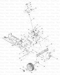
I am working on my Huskee (MTD) 148AR808K731 w/54" deck.
The steering is very sloppy.
I have replaced the tie rod ends,plastic bushings, steering shaft pinion bushing and the pinion.
Last season I replaced one of the bronze flange bushings that the steering gear rides on (the guide
bushing that rides in the arc shaped slot.)
I did not replace the front flange bushing in the steering gear.

I have also replaced the wheel bushings, but wobble still remains. Looks like time for new spindles.....

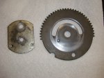
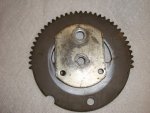
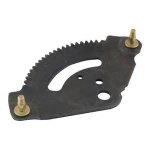
The steering gear, a more or less flat plate with teeth on the edge that the pinion gear meshes with is very wobbly/sloppy.
Is it this way by design?
There is a gap between the steering gear plate and the steering support bracket.
This permits considerable flop of the steering gear.
Is there any way to tighten this up?
A sheet of plastic between the steering gear and the support bracket?
If so, is it advisable?

The steering linkages are also sloppy on the plastic bushings.
Can these be tightened up?
They contact the plastic bushings at an angle. The linkage ends could be bent to be parallel with the steering gear
and a metal flange bushing installed, but would this be a problem when the front axle has to pivot with the terrain?
So, is it advisable??

Thanks in advance.
 

mhavanti

Well-Known Member
Joined
Oct 12, 2014
Threads
12
Messages
924
Ron,

I've found that you can add a piece of flat plastic of approximately .035 - .060 thickness between the top of the gear and the underside of the plate hold down will help with your sloppy steering. I've also found in one model and I can't remember the model of MTD made mower, I placed the plastic on the frame below the flat gear to raise the teeth into the shaft gear to engage them deeper. That also makes the gear move more easily against the plastic rather than metal to metal although you'll grease the two metals.

You can weld washers over the tie rod ends to tight them up. If you are an artist with a welder and grinder, you can make it look good and that will tighten your steering to the point of leaving the last slop in the spindles and front axles.

Another fix for the spindles and axle bushings is to take a good ole cold drink 2 liter bottle, cut a piece just long enough to make a inner bushing. I cut the two ends where they will meet at a 30 degree angle and then begin turning the wheel on the axle as you push the inner bushing in. It will get very tight, which is absolutely what you want. The plastic isn't going to wear out your axle or spindle and the slack will be totally gone. You can take all the slack out of the steering and it will also turn more freely making the use of one hand most of the time. As the inner bushings wears out over the years, the stiffness will begin coming back requiring two hands for sharp turns. That's the indicator that your trash cold drink bottles are needing replaced.

If you have a friend with a lathe, you can get a short piece of teflon rod and make the bushings and leave a one thousandth clearance. You can't do that with brass, however, teflon can actually function with zero clearance after you press it together. Not really conducive for most small shop operators or DYI repair folks. That's the reason I gave you the redneck method that works even with worn spindles and axles.

Have fun with it.

One of these days, I'm going to do a YouTube on the redneck repair. By the way, the bottle method I refer to is 4 years old in my 1996 Yard Man and still going strong. It could possibly make it another year before changing the inner bushings.

Good luck.
 

Ronno6

Lawn Addict
Joined
Apr 8, 2016
Threads
24
Messages
1,933
Thanks for all that great info!
A couple of questions:

Do you attach the plastic sheet to the support bracket or the gear (or,neither?)
Maybe just bore some holes where the flange bushings go to keep it in place?

When you mention raising the steering gear for deeper engagement with the pinion,
is that to say that the gap between the steering gear and the support bracket increases, which actually lowers the gear towards the ground?
That would require thicker plastic sheet and washers under the 2 guide bushings?

The washers for the tie rod ends I would think go on the ends with the plastic bushings...Correct?
Should the tie rods be bent to make the ends parallel to the steering gear?
(ed) After looking at them again, they are not that far out of parallel with the steering gear, if at all.

I think I need to use the pop bottle shim between the inner bushing and the wheel itself, as there is a bit of play there as well.

Thanks again!
 
Last edited:

mhavanti

Well-Known Member
Joined
Oct 12, 2014
Threads
12
Messages
924
Ron,

I'm attaching a couple of photos and I must first apologize for not showing the nylon shim I use. My neighbor walked in as I was preparing to take these photos. I already cleaned the grease from the gears and hold down plate, tearing apart the tool box looking for the nylon shims. He asked what I was doing, I told him and he laughed, said, you gave them to me middle of the mowing season last year. Oh well, you don't need them as you actually have a pattern for them sitting on your mower.

I'm posting the photos of the Steering Segment (flat gear) and the hold down plate along with a couple of diagrams. Bare in mind that mine may not be the exact same thing as yours, however, if yours has this type of set up, you can do this very easily. Just take your time and drill the holes tight enough to make it stay in place and not move around to allow grass, dust, dirt and grime in any more than necessary.

To hold down the geer and keep it from moving (flopping) around, place the nylon (plastic if that is all you can find) between the hold down plate and the gear segment. If your steering shaft gear is slightly angled from the mower frame, you can usually raise the gear segment a few thousandths to inset the teeth a bit deeper into the shaft gear. This will remove the slack from your steering at that point. It will also reflect in the overall however will not remove the slack in all your other moving joints.

You will notice the very normal wear on the items in the photos. Excellent wear pattern, none of the wear is into the metal measurable other than the parkerized finish of the metal. It had the MTD floppy gear syndrome. The unit it came off of needed every point tightened up and the mower had very little use at that point. Took out over 3/4 turn of the wheel to 11:30 to 12:30 on the wheel with all the slack adjustments. I mentioned in my first reply. The new bushings did nothing to remove any of the steering slack, thus, the ole Redneck Machining method was called for.

If you have further questions, feel free to give me a shout.

Max
 

Attachments

  • DSC04646.JPG
    DSC04646.JPG
    128.7 KB · Views: 53
  • DSC04647.JPG
    DSC04647.JPG
    136.9 KB · Views: 49
  • 1361614G401 (1996) MTD Yardman parts diagram.jpg
    1361614G401 (1996) MTD Yardman parts diagram.jpg
    235.3 KB · Views: 40
  • Steering Segment Blow Up.jpg
    Steering Segment Blow Up.jpg
    70.4 KB · Views: 36
Last edited:

Ronno6

Lawn Addict
Joined
Apr 8, 2016
Threads
24
Messages
1,933
Thanks.
Mine is a bit different.
The gear is pretty much flat and somewhat v-shaped on2 sides and arced where the teeth are.(Like a slice of pie.)
No retainer plate, just 2 flange bushings thru the pivot hole and the arc shaped groove like yours.

I'm attempting to attach the schematic, but don't know if it will work.

Thank you again!
 

Attachments

  • MTDsteering1.php.jpg
    MTDsteering1.php.jpg
    114.2 KB · Views: 35

Ronno6

Lawn Addict
Joined
Apr 8, 2016
Threads
24
Messages
1,933
Here is the gear itself.
It is #14 on the schematic
Tie rods attach over the studs.
 

Attachments

  • steeringgear.jpg
    steeringgear.jpg
    6.2 KB · Views: 19

mhavanti

Well-Known Member
Joined
Oct 12, 2014
Threads
12
Messages
924
That still seems pretty straight forward. Just fashion something to press the gear segment upward against your mower frame to hold it flat so that it doesn't move up and down. Each time it moves up and down when it is turned by the pinion gear (shaft gear), the two gears are unaligned and there is extra clearance between the teeth.
 

Ronno6

Lawn Addict
Joined
Apr 8, 2016
Threads
24
Messages
1,933
That still seems pretty straight forward. Just fashion something to press the gear segment upward against your mower frame to hold it flat so that it doesn't move up and down. Each time it moves up and down when it is turned by the pinion gear (shaft gear), the two gears are unaligned and there is extra clearance between the teeth.

Actually, If I want to minimize the play between steering gear and pinion, I need to move the steering gear downward.
The steering wheel shaft slants toward the steering gear, so I need to move the steering gear down.
Moving the pinion up will have no effect on clearance, as it will just travel along the axis of the shaft.
I have ordered some Delrin sheets and some 3/8" shims, as I will need to shim the guide bushings in order to lower the gear.

We'll see how it all works out.

Now, I guess I need to buy a 2-liter bottle of something...........

Thanks again.
 
Last edited:

mhavanti

Well-Known Member
Joined
Oct 12, 2014
Threads
12
Messages
924
That would be correct, moving it upward would be very difficult in your particular application since it is opposite of mine. lol. You can move your gear segment or what I prefer to call the ring gear lower as far as the slack in the built in washer on your bolt.
 

Ronno6

Lawn Addict
Joined
Apr 8, 2016
Threads
24
Messages
1,933
That would be correct, moving it upward would be very difficult in your particular application since it is opposite of mine. lol. You can move your gear segment or what I prefer to call the ring gear lower as far as the slack in the built in washer on your bolt.

I will be shimming under (over) the flanged guide bushings to drop the gear and tighten the steering.
I'll be adding a sheet of Delrin to remove the wobble........
Then work on the tie rods.

Right now I have removed the engine to gain access to the bolts and nuts that hold the steering gear in place, and to replace the main drive belt...
What a pain !
 
Top